This thread has been locked.

If you have a related question, please click the "Ask a related question" button in the top right corner. The newly created question will be automatically linked to this question.

AM2634: AM2634 is not booting in custom board

Part Number: AM2634

Tool/software:

Dear Team,

we made a custom board having AM2634 mcu and tring to flash the code by JTEG and by UART mode also, but unfortunately both mode are failed to flash the code,

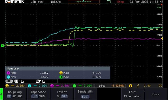
Here is voltage level on required pins

  PORz 3.3v
WARMRST 3.3
UART mode SOP0 3.3
SOP1 0
SOP2 0
SOP3 0
JTEG Pins connection X110 TMS  
TDI  
TDO  
TCK  
VTREF 3.3
Service Port A6,A7  

All required Vdd given to the MCU i.e 1.2v, 3.3v and 1.8v also generated by internal LDO of mcu but still mcu is running("C" is not coming on the service port terminal while configure the UART boot mode)

Debugger Error

rror connecting to the target:
(Error -1170 @ 0x0)
Unable to access the DAP. Reset the device, and retry the operation. If error persists, confirm configuration, power-cycle the board, and/or try more reliable JTAG settings (e.g. lower TCLK).
(Emulation package 9.13.0.00201)

we follow the steps as given in below link

(6) AM2634-Q1: ISSUE WITH JTAG PROGRAMMING FOR AM2634 - Arm-based microcontrollers forum - Arm-based microcontrollers - TI E2E support forums

So please suggest how to make it run

  • Hello,

    Are you able to change the boot mode configuration on your board? In addition, when you say you followed the steps in the other thread, do you mean you have confirmed via probe that all of your SOP pins are pulled correctly?

    Regards,

    Susan

  • Yes, all the SOP pin are confirm by DSO probe only, and i already shared current status of all the required pins to boot up the mcu

    power up sequece

    3.3v - channel-2 blue

    1.2v - channel-3 pink

    PORz - channel-1 yellow

    WARMRST - channel-4 green

    25 MHz crystal oscillator is connected in our board instead of TCXO,

    is it fine to get 'C' in UART mode or  TCXO required only

  • Hi,

    After changing 25Mhz to 8Mhz its started its started working,

    Now i want to know which configuration RBL(ROM bootloader )  doing for crystal detection mean is internal RC oscillator is ON at boot time or TCXO  or crystal configuration.

  • Hello,

    During Power-up, the internal RC oscillator is turned on after the power supply rails are stabilized. The full power on sequence is described in the TRM, in 6.2.2.1 PMU Reference System (REFSYS). It should remain on until a reset is triggered.
    The device shouldn't boot with an 8MHz crystal. Can you probe your crystal/oscillator and see what is the actual value and if it is stable?

    In addition, are you inputting the crystal into the XTAL IO pins or the external ref clock pin?

    Regards,

    Susan