Part Number: TMS570LS3137
Tool/software:
Hi there,
We are using the 144-pin PGE package of the MCU TMS570LS3137.
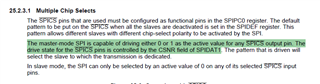
According to the device datasheet SPNS162C, the MibSPI5 peripheral in this package provides only 1x chip-select (CS0) to the outside, while the MCU has internally up to 4 CS (_nCS[3:0] for the BGA package, for example).
I'm looking for helps and confirmation for the following method to connect 2x SPI devices:
- Use the MibSPI1 CS0 to connect to one SPI device #1
- Tape an inverter to the CS0 line and connect its output to SPI device #2
- To exchange with device #1, pull down CS0 as normally do
- To exchange with device #2, raise CS0 by selecting any other CS (3, 2, or 1)
- Does the MCU allow this even when other CS signals are not routed to the outside?
Thank you very much!