This thread has been locked.

If you have a related question, please click the "Ask a related question" button in the top right corner. The newly created question will be automatically linked to this question.

AM263P2: Pin Mux Options

Part Number: AM263P2
Other Parts Discussed in Thread: TMDSHSECDOCK-AM263, SYSCONFIG

Tool/software:

Hello E2E Experts,

Good day

 am attempting to increase the number of PWM pins available to me on the AM263Px control card EVM through the use of pin multiplexing. I have been unable to do so, and I am unsure if it is a software issue that I am overlooking. I am using the TMDSHSECDOCK-AM263 for probing and debugging. CCS has been updated to the latest software version. I am able to get PWM signals on the dedicated PWM pins on the EVM (EPWM4_A, for example), but not on the pins that need to be configured as PWM through multiplexing. I will use EPWM28_A as an example, and the solution can likely be extended to other pins. The following is what I have attempted so far.  

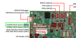
According to the datasheet, EPWM28_A is not a dedicated PWM pin, but is available by setting BALL M16 (pin 131) to Mode 5. This is shown below in the screenshots of the documentation for the EVM. 
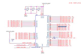
Pinout:

Multiplexing Options:

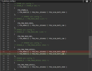
I then try to implement this in Code Composer Studio. In the "syscfg," I set up an instance of EPWM28 and select the pin that matches the documentation (M16). Checking the ti_pinmux_config.c file, I see that the auto generation correctly selects pin mode 5 to use it as a PWM pin.

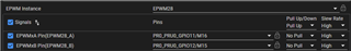
Auto Generated Pin Mux Code:

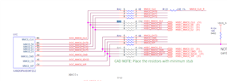
All the other settings (EPWM Time Base, EPWM Counter Compare, EPWM Action Qualifier, EPWM Dead-Band, etc...) are all identical to my EPWM0 instance, which I am able to get working. On the TMDSHSECDOCK-AM263 board, I am probing pin 131 (header J24_6). As of now, I am not receiving any PWM signal output. One concern that I have is that on the dock board, it labels pin 131 as GPMC0_A7, and not ICSS_MII0_TXD0 as it does on the EVM. Even in the EVM documentation, there is a difference between "Package Signal Name" and "Pinlist" for M16. I would assume that the pinouts (pin 131) should be the same between the dock and control card. 

I was under the impression that all the pin multiplexing would be done in the syscfg and not in the application code. Is this correct, or is there something that I am missing? 

Regards,

TICSC

  • Hi TICSC, 

    The reason for the differences in net names on the control card and dock is that the names used on each EVM indicate the primary use case of the net on the specific hardware platform. The net name is independent of the signal/pinmux mode you assign via SysConfig/software. The pinout itself is identical between the dock and control card.

    That being said, once you change the pinmux mode in SysConfig, are you rebuilding your CCS project before deploying the .out file to the control card?

    Regards,

    Brennan

  • Hello Brennan,

    Good day.

    After I make changes to the Syscfg, I enter debug mode for the project that I am working on without explicitly clicking the "rebuild project" command. This seems to work for the default PWM pins. Would you recommend rebuilding after each Syscfg change?

    I thought that the project was rebuilt when entering debug mode.

    Regards,

    TICSC

  • Hi TICSC, 

    Yes, please rebuild after syscfg changes. Let me know if this resolves your issue.

    Regards,

    Brennan

  • Hello Brennan,

    Good day.

    I have tried to rebuild the project after changing the syscfg. It still does not output a PWM signal. Even when I do not click rebuild and just enter debug mode, the dedicated PWM pins seem to follow my changes to syscfg. Can you verify that I am probing the correct pin number on the docking station and that the overall method/code sent in the first email is correct? I do not have any additional code to alter the PWM signals other than the syscfg setup that I sent previously.  
    Regards,
    TICSC
  • TICSC,

    There is a MUX upstream from the HSEC pin on the control card that controls the routing of the signal coming from AM263Px pin M16 to either the on-board Ethernet interface or to the HSEC pins:

    In order to route this signal to the HSEC connector, SEL1 of this mux needs to be pulled high. You can control this select signal using SW14. The default position of SW14 is LOW. Please try toggling SW14 to high and running your code again. You should now see the EPWM signal at the HSEC.

    Regards,

    Brennan

  • Hello Brennan,

    Good day.

    I was able to get a PWM signal on PWM17 from probing the unpopulated pad of RA3 on the control card. It appears that this is directly connected to the AM263P chip and does not require a multiplexing chip. In order to route this to the HSEC, can I just short the pads of RA3 together? Could I also do this for similar PWM channels? 

    Regards,

    TICSC

  • TICSC,

    Yes, you can short the pads on RA3 and RA5 to access signals from these pins at HSEC. I assume you are referring to these signals? You may want to remove RA2 and RA4 to avoid any stubs or signal reflections.

    Regards,

    Brennan