This thread has been locked.

If you have a related question, please click the "Ask a related question" button in the top right corner. The newly created question will be automatically linked to this question.

MSPM0L1117: Device ID doesnt match : Debug Mode IAR workbench 9.60.3

Part Number: MSPM0L1117
Other Parts Discussed in Thread: SYSCONFIG, UNIFLASH,
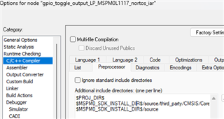
Tool/software:

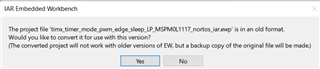
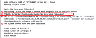
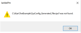
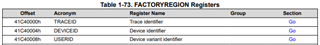
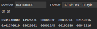
Another issue is  I am using IAR 9.60.03 workbench. My code builds successfully with MSPM0L1117. Here timers are not in PWM mode. With XMOL1117 Launchpad, when I click 'Download and Debug', it gives error Device ID doesnt match. Could you please let me know resolution?

  • Please try to import a IAR project from SDK.

    C:\ti\mspm0_sdk_2_04_00_06\examples\nortos\LP_MSPM0L1117\driverlib\timx_timer_mode_pwm_edge_sleep\iar

    And here is the guidance: https://dev.ti.com/tirex/explore/node?node=A__AEZVBSxqfwq5OekqjXGMyA__MSPM0-SDK__a3PaaoK__LATEST

    It will help you how to configure the IAR environment and how to import a SDK demo to IAR.

    I didn't see your linker file, .icf file in this project, not sure whether this project is valid or not.

    So, it's better to start from a SDK demo.

  • SDK is already installed, I still ensured all and followed your steps. Here are inputs. IAR pop-up project is in old format and need to convert to new version.

    Then when project is imported and MAKE is executed, it failed and below are screenshots for these. This uses GPIO poll example from SDK that you have mentioned.

    I tried to put more and more information so that you can check it. My finding is in project directory, .ipcf file is generated by the name of project itself that is lets say Project.eww then it generates file Project.ipcf and in output window it shows error Failed - SysConfig_Generated_Files.ipcf

    Also there is no SysConfig_Generated_Files.ipcf in project directory.

    Try to understand the issue ...Images are not clear after upload.

  • Same issue for timx_timer_mode_pwm_edge_sleep project also. This didnt work so I used GPIO to check.

  • Here is my IAR folder, .ipcf is from syscfg or you can manually copy it from SDK to your project folder.

    also, .icf is another file, this is linker file, used by linker.

    DeviceID may caused by your L1117 is XM0, X means early samples.

    You can try to use such as Uniflash/CCS to read MSPM0L1117's deivce ID region(factory region), to confirm whether this is correct or not.

  • Could you please provide example for  MSPM0L1117 ?. This is urgent, my development is delayed. Provide me complete solution. I will look into Device ID mismatch steps as you mentioned, first I need complete example code to successfully built. I would prefer you use 9.60.3 IAR workbench and MSPM0L1117. Are there any other supporting software's along with IAR workbench?  Provide detail steps. I would appreciate if you could reply in couple of hours. 

  • Build successfully.....hold on above comment. There is an issue with custom argument variables. Latest sysconfig version when installed is 1.23 where as it still uses path 1.22 when we provide SDK path. TI team need to fix it to installed version.

  • Here is the steps that I am doing:

    1. Crate a folder "E2E_L1117_Project" in desktop

    2. copy this folder to desktop folder.

    C:\ti\mspm0_sdk_2_04_00_06\examples\nortos\LP_MSPM0L1117\driverlib\gpio_toggle_output

    3. IAR, open workspace

    C:\Users\xxx\Desktop\E2E_L1117_Project\gpio_toggle_output\iar

    4. save eww file in:

    C:\Users\a0508911\Desktop\E2E_L1117_Project\gpio_toggle_output

    5. compiler, link and download to LP-MSPM0L1117 (XM0L1117)

    6. Here we go:

    Here is the project in desktop:

    E2E_L1117_Project.zip

  • This is the syscfg version when SDK is released.

    And updates of these two software are not synchronized.

  • Can you please check this and let me know if Device ID is correct or not? It gives error in debug mode in IAR. Jlink could read and connect. Using Launchpad XMOL1117.

    Connecting ...
    - Connecting via USB to probe/ programmer device 0
    - Probe/ Programmer firmware: J-Link V12 compiled Apr 1 2025 10:02:39
    - Probe/ Programmer S/N: 602005644
    - Device "MSPM0L1117" selected.
    - Target interface speed: 4000 kHz (Fixed)
    - VTarget = 3.300V
    - InitTarget() start
    - DAP initialized successfully.
    - Setting up LPM debug bits
    - InitTarget() end - Took 2.49ms
    - Found SW-DP with ID 0x6BA02477
    - DPIDR: 0x6BA02477
    - CoreSight SoC-400 or earlier
    - Scanning AP map to find all available APs
    - AP[5]: Stopped AP scan as end of AP map has been reached
    - AP[0]: AHB-AP (IDR: 0x84770001, ADDR: 0x00000000)
    - AP[1]: MEM-AP (IDR: 0x002E0001, ADDR: 0x01000000)
    - AP[2]: JTAG-AP (IDR: 0x002E0000, ADDR: 0x02000000)
    - AP[3]: MEM-AP (IDR: 0x002E0003, ADDR: 0x03000000)
    - AP[4]: MEM-AP (IDR: 0x002E0002, ADDR: 0x04000000)
    - Iterating through AP map to find AHB-AP to use
    - AP[0]: Core found
    - AP[0]: AHB-AP ROM base: 0xF0000000
    - CPUID register: 0x410CC601. Implementer code: 0x41 (ARM)
    - Found Cortex-M0 r0p1, Little endian.
    - FPUnit: 4 code (BP) slots and 0 literal slots
    - CoreSight components:
    - ROMTbl[0] @ F0000000
    - [0][0]: E00FF000 CID B105100D PID 000BB4C0 ROM Table
    - ROMTbl[1] @ E00FF000
    - [1][0]: E000E000 CID B105E00D PID 000BB008 SCS
    - [1][1]: E0001000 CID B105E00D PID 000BB00A DWT
    - [1][2]: E0002000 CID B105E00D PID 000BB00B FPB
    - [0][2]: 40402000 CID B105900D PID 001BB932 MTB-M0+
    - Executing init sequence ...
    - Initialized successfully
    - Target interface speed: 4000 kHz (Fixed)
    - Found 1 JTAG device. Core ID: 0x6BA02477 (None)
    - Connected successfully

  • This is in TRM

    This is read from L1117

    Device ID from my Launchpad is 0BBB402F

    If you don't want to modify nonmain, please don't enable this part

    No issue use Jflash from my side.

    Please try the latest version of JFlash

  • Can you please check on IAR workbench? It is giving error Device ID doesnt match.

    How can I read this ID using J-Link? I didnt see any option where I can see the Device ID.

  • You can see my previous reply, already run L1117 in IAR.

    You can read device ID from this address.

  • Are you using C-SPY?

  • This is the function from CCS, memory browser window.

    Also, do you have any other L1117 to test?

    What's the debugger you are using? From My side, I try to connect L1117 using J-link and J-flash, also XDS110 on launchpad and CCS.

  • You are not reading my message carefully...I have mentioned multiple times that I am using IAR ang J-Link.

    Also your SysConfig utility has issues. I have configured timer G1 to generate PWM signal, no output on pin. Below incomplete code is generated.

    Please check and provide solution.

    Warning[Pa084]: pointless integer comparison, the result is always false C:\ti\iar\2505_Project\ti_msp_dl_config.c 93
    Error[Pe020]: identifier "DL_TIMER_CZC_CCCTL_ZCOND" is undefined C:\ti\iar\2505_Project\ti_msp_dl_config.c 301
    Error[Pe020]: identifier "DL_TIMER_CAC_CCCTL_ACOND" is undefined C:\ti\iar\2505_Project\ti_msp_dl_config.c 301
    Error[Pe020]: identifier "DL_TIMER_CLC_CCCTL_LCOND" is undefined C:\ti\iar\2505_Project\ti_msp_dl_config.c 301
    Error[Pe029]: expected an expression C:\ti\iar\2505_Project\ti_msp_dl_config.c 309
    Error[Pe020]: identifier "DL_TIMER_CZC_CCCTL_ZCOND" is undefined C:\ti\iar\2505_Project\ti_msp_dl_config.c 340
    Error[Pe020]: identifier "DL_TIMER_CAC_CCCTL_ACOND" is undefined C:\ti\iar\2505_Project\ti_msp_dl_config.c 340
    Error[Pe020]: identifier "DL_TIMER_CLC_CCCTL_LCOND" is undefined C:\ti\iar\2505_Project\ti_msp_dl_config.c 340
    Error[Pe029]: expected an expression C:\ti\iar\2505_Project\ti_msp_dl_config.c 346

    SYSCONFIG_WEAK void SYSCFG_DL_RelayPWM_TimerG1_init(void) {

    DL_TimerG_setClockConfig(
    RelayPWM_TimerG1_INST, (DL_TimerG_ClockConfig *) &gRelayPWM_TimerG1ClockConfig);

    DL_TimerG_initPWMMode(
    RelayPWM_TimerG1_INST, (DL_TimerG_PWMConfig *) &gRelayPWM_TimerG1Config);

    // Set Counter control to the smallest CC index being used
    DL_TimerG_setCounterControl(RelayPWM_TimerG1_INST,DL_TIMER_CZC_CCCTL_ZCOND,DL_TIMER_CAC_CCCTL_ACOND,DL_TIMER_CLC_CCCTL_LCOND);

    DL_TimerG_enableClock(RelayPWM_TimerG1_INST);


    DL_TimerG_enableInterrupt(RelayPWM_TimerG1_INST , DL_TIMER_INTERRUPT_OVERFLOW_EVENT);

    NVIC_SetPriority(RelayPWM_TimerG1_INST_INT_IRQN, 1);
    DL_TimerG_setCCPDirection(RelayPWM_TimerG1_INST , );


    }

  • Please check SysConfig issue and provide solution earliest. Timer G1 and G8 are configured in PWM mode no output on pin.

    Incomplete code generation : 

    DL_TimerG_setCCPDirection(RelayPWM_TimerG1_INST , )

    Undeclared macros: 

    Error[Pe020]: identifier "DL_TIMER_CZC_CCCTL_ZCOND" is undefined C:\ti\iar\2505_Project\ti_msp_dl_config.c 340
    Error[Pe020]: identifier "DL_TIMER_CAC_CCCTL_ACOND" is undefined C:\ti\iar\2505_Project\ti_msp_dl_config.c 340
    Error[Pe020]: identifier "DL_TIMER_CLC_CCCTL_LCOND" is undefined C:\ti\iar\2505_Project\ti_msp_dl_config.c 340

  • You are not reading my message carefully...I have mentioned multiple times that I am using IAR ang J-Link.

    I got same issue in IAR with Jlink, I will try to fix this, need sometimes...

    I recommend you to use XDS110 on Launchpad first, because this fix may takes some time.

  • Also your SysConfig utility has issues. I have configured timer G1 to generate PWM signal, no output on pin. Below incomplete code is generated.

    Please check and provide solution.

    I didn't see this in my IAR with L1117.

    Please check whether these path is valid or not:

    I can jump from these macro to dl_timer.h in SDK 2.04.00.06

  • Please check SysConfig issue and provide solution earliest. Timer G1 and G8 are configured in PWM mode no output on pin.

    It's maybe caused by these undefine issue.

    Als0. please check your hardware connect, if you are using the launchpad, please check schematic and jumper.

    Here is my project that there is no compiler issue.

    gpio_toggle_output.zip

  • Please try to disable this, and I think you can use Jlink with IAR now.

  • Great. Device ID mismatch is no more now. Thank you. 

    Regarding PWM issue, your code "gpio_toggle_output" uses PWM channels 0 and 1 and provides output on pins.

    I do not want any pin to be controlled. I only want to have interrupts based on Period resistor so that I can use interrupt to execute operation.

    I observed that if I do not select PWM channel then above mentioned issue occurs. 

    Please let us know how can I generate PWM interrupts of G1 and G8 without using any PWM channel and IO.

    Please configure G1 and G8 for 1 Khz and 50% duty cycle and no PWM channel selection, no any I/O pin and generate interrupt. You will come face same issue that I am facing.

    Please check this and reply me earliest.

  • Based on basic PWM demo I sent you, disable timer PWM output function in this register

    23.3.32 ODIS (Offset = 1104h) [Reset = 00000000h]

    Also, you need to reset the IOMUX.

  • You have sent 

    Your code uses PA15 and PA16 pins, channel 0 and 1. I want PWM mode G1 and G8 timers and no any pin and PWM channel. 

    Code generated by TI System Config uses undeclared macros and incomplete function. 

    If I modify any code in generated .c files, it gets cleared on next build as new files are created.

    I want interrupts for these G1 and G8 PWM timers on period match with no PWM channels selection. Can you please take efforts and provide the above mentioned code 1KHz, 50% duty cycle G1 IRQ interrupt with no any PWM channel and pin selection? 

    This query is pending since a week, please provide solution and resolve earliest.

  • You can add the IOMUX reset and ODIS function just after SYSCFG_DL_init in main.

  • What about below errors? Provide resolution to it.

    Incomplete code generation : 

    DL_TimerG_setCCPDirection(RelayPWM_TimerG1_INST , )

    Undeclared macros: 

    Error[Pe020]: identifier "DL_TIMER_CZC_CCCTL_ZCOND" is undefined C:\ti\iar\2505_Project\ti_msp_dl_config.c 340
    Error[Pe020]: identifier "DL_TIMER_CAC_CCCTL_ACOND" is undefined C:\ti\iar\2505_Project\ti_msp_dl_config.c 340
    Error[Pe020]: identifier "DL_TIMER_CLC_CCCTL_LCOND" is undefined C:\ti\iar\2505_Project\ti_msp_dl_config.c 340

  • There compiler error didn't shown at my side.

    Please check you IAR project include path.

    Compare it with the project I send you.

    Do you see any error when you use the project I sent you?

    These macro are defined in source - driverlib in MSPM0SDK

  • From an offline email exchange:

    "

    Device mismatch ID is resolved now. IAR Workbench works fine now.

    ALSO ---

    TI code configurator generates code that is giving build errors for undeclared macros generated by configurator. This is when we configure timers in PWM mode without any channel I/O selection. (We do not need any PWM signal on pin, we manually select those relay pins)

    On forums, the TI team mentioned to configure PWMs with pin selections but then reset this selection at the time of initialization to achieve the same functional operation; PWM  configuration without any output on pins.

     Right now we have configured timers in non PWM mode and continuing our next development. Once all code integration is completed, we would again look into this as we didn’t want to spend more time on that issue at this point.

    "

    TY,

    Chris

  • Yes, this is also a method, configure timer to timer mode and manually add CC function to this timer.

     Right now we have configured timers in non PWM mode and continuing our next development.