This thread has been locked.

If you have a related question, please click the "Ask a related question" button in the top right corner. The newly created question will be automatically linked to this question.

MSPM0G3507-Q1: Arm-based microcontrollers forum

Part Number: MSPM0G3507-Q1


Tool/software:


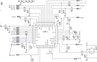
Hello! When I was debugging CAN communication, I encountered a situation where CAN_TX remained at a high level all the time. This is my hardware design. The program I wrote myself can communicate normally on the Demo board of TI. If it is used on the board designed by oneself, communication cannot be achieved, and CAN_TX remains at a high level all the time. Please help analyze whether there are any issues with the above circuit design, what points should be noted for the CAN communication of the M0G3507 chip, and what directions for troubleshooting are provided. Thank you!

  • Hi, from MCU side, only connect MSPM0 Tx to CAN transceiver Tx, and Rx to Rx is ok.

    Here is some test need to do from MCU side:

    1. need to confirm whether MCU can run into main function and finishe init.

    2. Rosc resistor is 1% 100k, we recommend you to use 0.1% resistor to get better SYSOSC accuracy.

    3. PA18 is BSL invoke pin, need to add pulldown resistor. When powering up or reset, if PA18 is high, MSPM0 will enter BSL mode.

        you can disable PA18 BSL check in nonmain(NVM configuration in syscfg, but there is risk to modify nonmain)

    Since you have verify the software code based on TI demo board, please check if there are any issue on CAN transceiver side.

    You can try to get some help from NSI1042.

  • On my board, I disconnected the M0 from the CAN transceiver for testing. When observing the CAN_TX pin of the M0 with an oscilloscope, the pin voltage remained high all the time. On the demo board, however, this pin showed data transmission. As for the third point you mentioned, I externally connected a test pin, which worked properly. I'd like to verify if there is specific hardware configuration required to enable the CAN peripheral function for the CAN transceiver of this chip.

  • I'd like to verify if there is specific hardware configuration required to enable the CAN peripheral function for the CAN transceiver of this chip.

    For the M0?

    If you can run can normally on demo board, save code should workable on your customer board.

    Because:

    As for the third point you mentioned, I externally connected a test pin, which worked properly

    M0 have already run into your applicaition code.

    Have you try to do any debug on M0?

    to check CAN status? or stuck at somewhere else?