This thread has been locked.

If you have a related question, please click the "Ask a related question" button in the top right corner. The newly created question will be automatically linked to this question.

MSPM0G1507: How can PWM synchronisation delay times be reduced ?

Expert 2410 points
Part Number: MSPM0G1507
Other Parts Discussed in Thread: SYSCONFIG, MSPM0G3507

Tool/software:

Hi All,

I am trying to synchronise TIMA0(C0) and TIMG7(C0).
Immediately after the PWM output starts, they are synchronised, but if I change the Period and Duty in the interrupt handler of the ZERO event of TIMG7, the phase shifts.
How can the delay time be reduced?

We assume that this is because the next
period comes while changing the period and duty cycle due to the delay in the generation of the ZERO event.

[Conditions]

- TIMA0 and TIMG7 are down-counted.
- The operating frequency is 32 MHz.
- The PWM period gradually decreases from 100 KHz to 20 KHz.
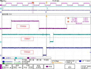
- TIMA0 and TIMG7 are synchronised using TIMG6 to cross trigger.
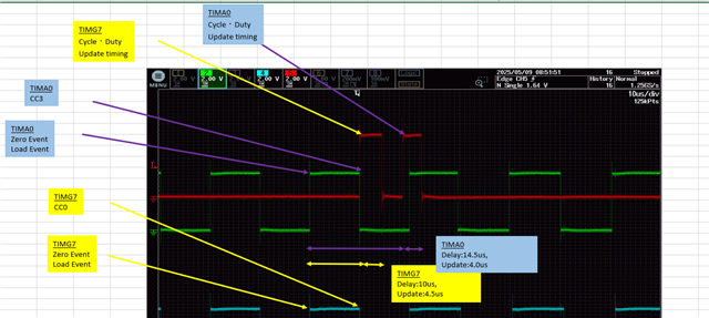
- In Interrputs Configuration of TIMG7, select "ZERO Event" is selected and the next cycle and Duty are set in the interrupt handler.

-Waiting time from event generation to start of processing is 2~48 µs.
-Processing time in the interrupt handler is approx. 5 µs.

-Systick and ADC were set Low and TIMG7 was set High in SysConfig, but no change.
- ADC interrupts were completely stopped, but no change.
- Tried using LOAD event and Channel 0 capture or compare down zero event instead of ZERO event, but no change.
- Checked ‘Enable Shadow Load’ in SysConfig, but no change.
- Changed Channel Update Mode, but no change.

Best Regards,

Ito

  • Hi lto,

    Any waveform you can show up here for my reference?

    What the cross trigger method you are using, software trigger?

    B.R.

    Sal

  • Hi Sal,

    Thank you for your help.

    I have sent the data to your private message.

    Best Regards,

    Ito

  • Hi Ito,

    Thanks for clarification on the message.

    I don't find the sysconfig files, so that I am not sure how you configure the timers. While I see select TIMG7 and TIMA0, so that I am assuming you are using the shadow CC and shadow Load to update the PMW period and duty. 

    - Then, what trigger method you are using with shadow CC and Load? Are you using the zeor event?

    Then, as you want to sync TIMA0 and TIMG7, I see you used TIMG6 to cross trigger.

    - Why there requires TIMG6, directly use TIMG7 to trigger TIMA0 looks more simple. 

    - BTW, are TIMA0 and TIMG7 has the same period all the time?

    -Waiting time from event generation to start of processing is 2~48 µs.
    -Processing time in the interrupt handler is approx. 5 µs.

    What the waiting time of the event generation? Would you mean the delay for interrupt entry?

    2us is okay, while 48us looks not reasonable one.

    Additionally, what the red line it represent for?

    I am not getting your point how you do judgement the delay time. Are you using a GPIO to toggle in the TIMG7 interrupt, and then you find the timing update in the interrupt is quite late than expected? -> Please correct me if I misunderstanding.

    Then where you update the TIMA0 duty and period? Also in the TIMG7 interrupt but with a delay due to the processing task for calculate the duty?

    B.R.

    Sal 

  • Hi Sal,

    Thank you for your help.

    I sent you a Sysconfig ScreenShot in a private message.
    Questions will be confirmed with the customer.

    Best Regards,

    Ito

  • Hi Sal,

    Thank you for your reply.

    - Then, what trigger method you are using with shadow CC and Load? Are you using the zeor event?

    Yes

    - Why there requires TIMG6, directly use TIMG7 to trigger TIMA0 looks more simple. 

    This is because the Clostrigger sample code is synchronised using a timer other than PWM output.

    - BTW, are TIMA0 and TIMG7 has the same period all the time?

    Yes

    Additionally, what the red line it represent for?

    We output PA31 to Hi at the start of processing within the interrupt handler and to Lo at the end of processing, and monitor it with an oscilloscope.

    I am not getting your point how you do judgement the delay time. Are you using a GPIO to toggle in the TIMG7 interrupt, and then you find the timing update in the interrupt is quite late than expected?

    No processing is performed to switch TIMG7 interrupts.

    Then where you update the TIMA0 duty and period?

    Update within the TIMG7 interrupt handler.

    Also in the TIMG7 interrupt but with a delay due to the processing task for calculate the duty?

    Duty calculation is performed in the main process, and the settings are made in the interrupt handler.

    I sent you the documnt in your private messege.

    Best Regards,

    Ito

  • Hi Sal,

    How is your progress coming along?
    Please give me some advice.

    Best Regards,

    Ito

  • Hi Sal,

    There has been progress in customer testing.

    I will send you the sample code via private message.

    We investigated the causes of the delay by reflecting the settings changed by our company based on the sample source code.

    Sample: timx_timer_mode_pwm_edge_sleep_shadow_LP_MSPM0G3507_nortos_ticlang
    ・Added PA3 as GPIO.
    ・Measured time by turning port output ON/OFF.

    ・Reflected the differences between the sample and customer project on SysConfig
    and applied them to the sample, but there was no delay in the sample.
    • In the customer project, delays and variations in delay times occurred.
    • Next, we focused on the differences in interrupt handling between the sample and the customer project,
    and added SysTick to the sample, but the results remained unchanged.
    • Since ADC was being processed by interrupt, we stopped ADC, but the results remained unchanged.
    • No interrupts were used except for SysTick, ADC, and Timer.

    ・As a precaution, we checked the PWM zero event occurrence flag via polling, and found that the zero event occurrence was delayed by approximately 1.5us.
    ・In the sample project, when interrupts were used, the interrupt handler processing started in less than 1us, so we would like to use interrupts if possible.

    [Question]
    Please let us know if there are any settings that cause a delay in the time between the zero event occurring and the interrupt processing starting. We will change those settings.

    Best Regards,

    Ito

  • Hi Ito,

    Sorry for late response. I have checked your message and done some test for this scenario. And I do see the deviation on the phase between TIMA0 and TIMG7 when dynamically update the period and duty cycle.

    And I check this only related to period modification behavior, duty doesn't impact the phase.

    The reason I am thinking that load behavor by the shadow LOAD register might contributes some timing deviation, so the phase shift occurs. And software trigger only sync the timer instance at first, after they started, it will not generate the cross trigger signal unless user add it in the application code and periodically call the API.

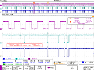
      [After modify several times of the period, phase shift shows up]

    My suggestion is use TIMG7 to trigger TIMA0 directly and set the EVEVNT trigger mode as zero, so that it will be synced every PWM cycles.

    One thing is that, it requires to set LOAD as interrupt resource, as user has set shadow CC and shadow Load functions, which triggered by ZERO EVENT, there might have register contention, and lost some period update [I have obeserved this issues if set ZERO as interrupt source].

    -> Haven't dig it deeply, just some rough idea.

    Attached the test project as your reference. I find a bug that the sysconfig tool generated code has issues, so I manually fix it in the exmaple project by exclude the generated source file.

    CrossTrigger_Test_G3507.ZIP

    Please let me know if you have further questions, thanks.

    B.R.

    Sal

  • Hi Sal,

    Thank you for your help.

    This issue has been resolved.

    Best Regards,

    Ito