Part Number: AM2432
Tool/software:
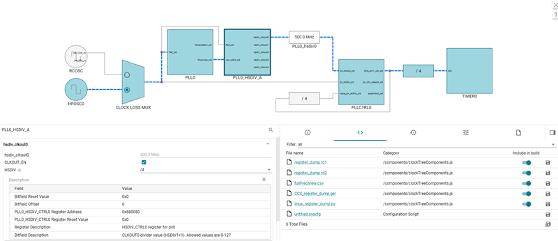
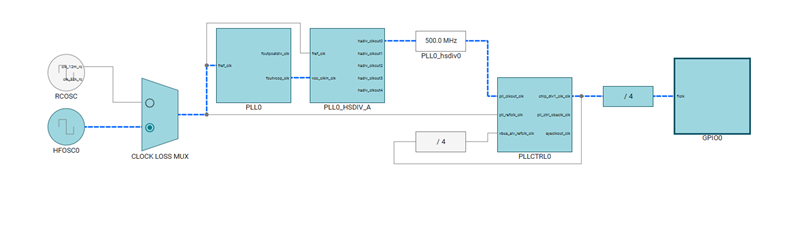
I need to evaluate Sitara AM2432 GPIO pin's 800MHz signal that is committed in datasheet.
My understanding is to use PLL to turn the 25MHz reference clock to generate the high speed output.
It is hard to find the API functions in manual to control PLL.
And there is no good example code in SDK example library.
Can you please suggest me the procedure and share the APIs to implement this function.
Additionally, if I need to further divide the 800MHz signal to specific frequence for other functions, please share procedure if available.
Thanks.
Thanks & Best regards
Hao (Wang hao)