Other Parts Discussed in Thread: UNIFLASH, SYSCONFIG
Tool/software:
Hey Experts,
ive some question regarding the resolver module.
As SW i am using:
CCS 12.8.1.00005
SDK 10_00_00_35
Uniflash 8.8.1.4983
As HW ive a custom board.
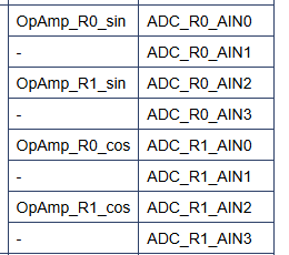
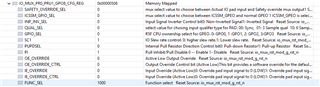
Here is my config for the resolver: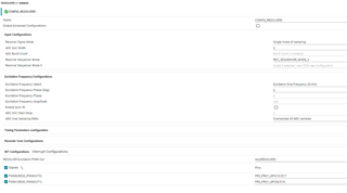
Here are my HW connections: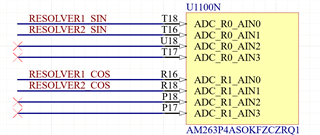


A resolver is only connected to RESOLVER1.
1) As Excitation PWM Out ive selected 2 pins. regarding this post:https://e2e.ti.com/support/microcontrollers/arm-based-microcontrollers-group/arm-based-microcontrollers/f/arm-based-microcontrollers-forum/1345059/am263p4-does-the-resolver-support-output-differential-pwm
its the same output just at 2 pins. My problem is, that i can see the excitation PWM at PWM0, but at PWM1 there is just 0V (checked HW, there is no short zo GND at this line). Any ideas, why i don't see the excitation PWM there?
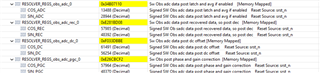
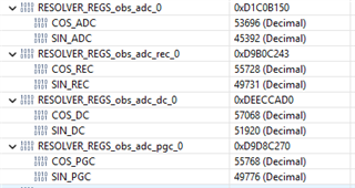
2) Nevertheless if i check the resolver 2 registers i see the following values: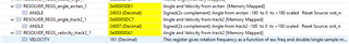
which change if i turn the resolver which is only connected to resolver 1.
If i measure the voltage at pcb with oscilloscope at RESOLVER2 SIN or RESOLVER2 COS its flat 1.65V (reference voltage for input amplifier).
So i would expect stable values for the angle and velocity.
Do you have any idea why the values change?
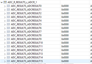
Can i check the measured raw ADC values in any register? I only found the calculated arctan and track2 values i posted above.
Best regards,
Marcel