Part Number: TM4C123GE6PM
Other Parts Discussed in Thread: TM4C123GH6PM
Tool/software:
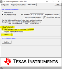
We have moved from the LaunchPad and created our own board. Programming via FTDI-USB over serial UART0 is working using LM Flash Programmer for our board.
I used the code from the samples to blink a light and if SW1 switch is clicked it launches bootloader. If I were to accidently not upload the correct code with something to enable the bootloader is it possible to start the bootloader?
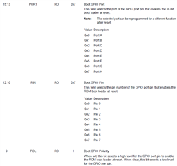
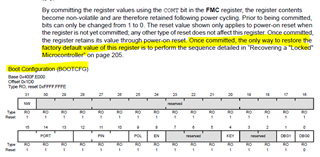
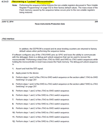
Is there a default configuration for a blank chip to enable the bootloader? For instance by default is BOOTCFG set so that I can raise a pin high to get bootloader to run? I just want to be sure that I do not brick the first prototype that we have created.
Thanks in advance!