Part Number: LP-MSPM0G3507
Other Parts Discussed in Thread: MSPM0G3507, DRV8316, SYSCONFIG
Tool/software:
Hello Ti,
I am having the following issues when trying to run my PMSM motor using DRV8316_EVM with MSPM0G3507 + SDK 2_04_00_06 :
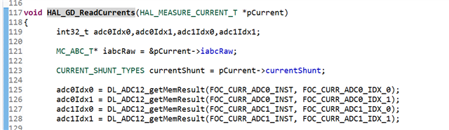
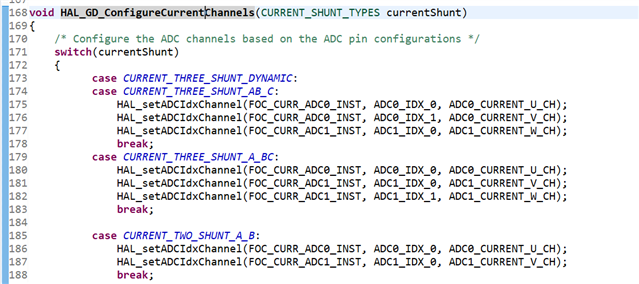
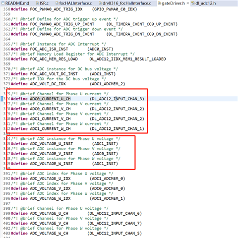
1-In sysconfig i can't see the ADC configurations for current sensing in i can see only ADC0_7, ADC1_6 and ADC1_3 are the only channels configured.
2-"maximum speed" system parameter is the no load speed or at which mechanical speed i should calculate it?
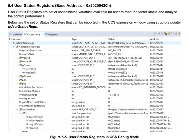
3-Can i debug in transition between states, for e.g i can't debug where the motorState variable is changing in sensorless version of the code is this provided as some library not open code?
4-Motor is able to reach open loop state and stay operational in it but whenever i try to move to closed loop (closeLoopDis = 0) it stops with Stall fault (abnormal emf lock -> it is the only enabled lock) and also i observe that the open loop current is higher than the reasonable values although i am tuning the OLilimit and i made Kp and KI params = 0 and I made sure the back emf is measured manually and i multiplied it by 10 as stated in the manual.
5- Do i need to configure the BaseVoltage as 44.59 in the GUI or 25.77 as i see in ISR.c in the default case it should result to MOTOR_VOLTAGE_BASE = 25.77 which will lead to pUserInputRegs->systemParams.voltageBase = MOTOR_VOLTAGE_BASE (i.e 25.7).......... while if i configured it in GUI directly as 44.59 it will be pUserInputRegs->systemParams.voltageBase = 44.59
Finally the correct Base voltage equation In the MSPM0 Sensorless FOC tunning guide should be 3.3V / (R2 / (R1 + R2)) which is 44.27 instead of 3.3V / (R1 / (R1 + R2)) which is 3.5 correct?
Thank you,