This thread has been locked.

If you have a related question, please click the "Ask a related question" button in the top right corner. The newly created question will be automatically linked to this question.

TM4C1231E6PZ: For SSI0 peripheral supports DMA?

Part Number: TM4C1231E6PZ
Other Parts Discussed in Thread: EK-TM4C123GXL

Tool/software:

Hi TI,

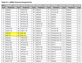
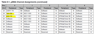
I'm using the TM4C1231E6PZ MCU and i want to know if the SSIO supports the DMA rx feature in this series?

Please confirm if this works or not? if yes which example i can take?

Thanks & Regards,

Manoj.

  • Hi,

      TM4C1231E6PZ supports DMA for SSI module. You can find uDMA example at C:\ti\TivaWare_C_Series-2.2.0.295\examples\boards\ek-tm4c123gxl\udma_demo. This example demonstrates using uDMA to transfer data between memories and also between UART and memory. You should be able to reference the example and modify for SSI module base on the channel mapping for SSI as shown in the datasheet for uDMA usage. 

  • Hi Charles,

    I'm using the CCS version 20.1.1 version. I'm facing the source code debug in this version results are not same. sometimes it works and without modification of code it won't work. 

    I'm difficult to point what is the issue and idea or any stable versions of ccs ide where i can use the code generator option efficiently. in this I'm unable to generate the clock from the .syscfg 

    I tried the examples as well in my custom board having TM4c1231e6pz microcontroller. the example was modified as per your comment on previous response question. 

    Please Share me any related documents on how to use the CCS for code generation and clock generation. Let me know your thoughts on this.

    Thanks & regards,

    Manoj.

  • Hi,

    I'm using the CCS version 20.1.1 version. I'm facing the source code debug in this version results are not same. sometimes it works and without modification of code it won't work. 

    CCS20 is the latest IDE that is based on Theia. What type of issue do you have when debugging source code? Please elaborate. If you are trying to single step the code and find that the code kind of jumping back and fourth, that is the because of the compiler optimization. You can turn off the optimization during code development and turn it on once the code is frozen. If this is not your issue then please elaborate so I can forward your question to our toolchain expert. It will be better that you open a new thread for CCS problems.

    I'm difficult to point what is the issue and idea or any stable versions of ccs ide where i can use the code generator option efficiently. in this I'm unable to generate the clock from the .syscfg 

    The .syscfg is mainly for TI MCU/MPU that are based on SimpleLink SDK. There is no benefit to use .syscfg for TM4C MCU as it is based on the TivaWare SDK. What .syscfg can do for TM4C MCU is only the pinmuxing. You cannot use .syscfg for clock or peripheral configuration. To configure the clock for TM4C123, it is simply calling the SysCtlClockSet() API. See below example to configure the System Clock for 50Mhz using PLL as the clock source. Please download TivaWare SDK from https://www.ti.com/tool/SW-TM4C. You can find examples for TM4C123 under C:\ti\TivaWare_C_Series-2.2.0.295\examples\boards\ek-tm4c123gxl. Import any one of the projects to have a feel how clock and peripherals are initialized. 

    //
    // Setup the system clock to run at 50 Mhz from PLL with crystal reference
    //
    SysCtlClockSet(SYSCTL_SYSDIV_4|SYSCTL_USE_PLL|SYSCTL_XTAL_16MHZ|
    SYSCTL_OSC_MAIN);

  • hi Charles,

    I faced the following issues,

    1. Soon after ide enters into debug mode, firmware run will be halted immediately. How many times we start debug there will be no response. if i perform the core reset or board reset then the debug mode will work in smooth way.

    2. The Firmware consists of timer interrupts and SPI0 dma interrupt. The behaviour of firmware is like when i try the same firmware debug three times, 2times the timer never generates the interrupt and 1 time it will generate the interrupt.

    in my current firmware i used the clock init like this 

        SysCtlClockSet(SYSCTL_SYSDIV_4|SYSCTL_USE_PLL|SYSCTL_OSC_MAIN |SYSCTL_XTAL_16MHZ);
     
     
    Let me know your comments on the above scenarios i faced through the latest version of CCS.
    Thanks & regards,
    Manoj.
  • 1. Soon after ide enters into debug mode, firmware run will be halted immediately. How many times we start debug there will be no response. if i perform the core reset or board reset then the debug mode will work in smooth way.

    When the debugger halts the processor, the processor will be unable to service the interrupt. This is the expected behavior. You might even get a Receive Overrun flag because the RXFIFO is overwritten with new data but the processor is halted and unable to read the previous data in the FIFO.

    2. The Firmware consists of timer interrupts and SPI0 dma interrupt. The behaviour of firmware is like when i try the same firmware debug three times, 2times the timer never generates the interrupt and 1 time it will generate the interrupt.

    I don't understand what you mean for the timer interrupt to not generate for two times. Why don't you put a breakpoint on the timer ISR? Does it halt at the breakpoint?