This thread has been locked.

If you have a related question, please click the "Ask a related question" button in the top right corner. The newly created question will be automatically linked to this question.

MSPM0G3519: SPI controller's frame format mode moto4_pol0_phaX

Part Number: MSPM0G3519


Tool/software:

Hello colleagues, i have a question concerning behavior of the SPI controller in controller mode, particularly setting

DL_SPI_FRAME_FORMAT which has options: 

DL_SPI_FRAME_FORMAT_MOTO3_POL0_PHA0 

Motorola 3 Wire with Polarity 0, Phase 0

DL_SPI_FRAME_FORMAT_MOTO3_POL0_PHA1 

Motorola 3 Wire with Polarity 0, Phase 1

DL_SPI_FRAME_FORMAT_MOTO3_POL1_PHA0 

Motorola 3 Wire with Polarity 1, Phase 0

DL_SPI_FRAME_FORMAT_MOTO3_POL1_PHA1 

Motorola 3 Wire with Polarity 1, Phase 1

DL_SPI_FRAME_FORMAT_MOTO4_POL0_PHA0 

Motorola 4 Wire with Polarity 0, Phase 0

DL_SPI_FRAME_FORMAT_MOTO4_POL0_PHA1 

Motorola 4 Wire with Polarity 0, Phase 1

DL_SPI_FRAME_FORMAT_MOTO4_POL1_PHA0 

Motorola 4 Wire with Polarity 1, Phase 0

DL_SPI_FRAME_FORMAT_MOTO4_POL1_PHA1 

Motorola 4 Wire with Polarity 1, Phase 1

DL_SPI_FRAME_FORMAT_TI_SYNC 

TI Sync Frame Format

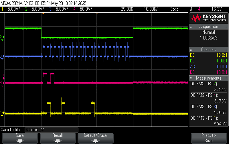
(in both cases FIFO has 3 bytes of data 0xA00000 - and it is clearly seen on the OUT of the waveform)

if the option DL_SPI_FRAME_FORMAT_MOTO4_POL0_PHA1 is selected the following controller behavior is observed (green - CS, blue - SCLK, purple - OUT)

but if

DL_SPI_FRAME_FORMAT_MOTO4_POL0_PHA0
the situation is completely different:

does it matches what the documentation tells about this feature? please advise
  • I suppose you're referring to the de-assertions of /CS between bytes.

    This distinction is described in TRM (SLAU846B) Sec 19.2.3.1 -- search for "continuous back-to-back". In one case (SPH=1) /CS "is held low", and in the other (SPH=0) /CS "must be pulsed high" between bytes.

    This is one of a few reasons to not use the built-in chip selects, but rather implement /CS using a GPIO.