Part Number: TM4C129ENCPDT
Tool/software:
Hello,
I am facing an issue with getting the Tx interrupt to trigger at the end of the transmission. I am working with a half-duplex transceiver so I need to toggle a GPIO as soon as I am done with the transmission to get it to start receiving.
Below is the code I have written for the UART setup:
UARTTxIntModeSet(UART4_BASE, UART_TXINT_MODE_EOT);
UARTIntClear(UART4_BASE, UART_INT_TX | UART_INT_RX | UART_INT_RT);
UARTEnable(UART4_BASE);
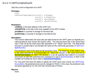
UARTConfigSetExpClk(UART4_BASE, SysCtlClockGet(), 115200, (UART_CONFIG_WLEN_8 | UART_CONFIG_STOP_ONE | UART_CONFIG_PAR_ODD));
UARTFIFOEnable(UART4_BASE);
Below is the function that sends the data:
void ModbusVFD::RequestData(uint16_t address) {
GPIOPinWrite(GPIO_PORTK_BASE, GPIO_PIN_2, GPIO_PIN_2); //Toggle the GPIO on before sending
uint8_t buffer[8];
buffer[0] = 0x01; // slave address
buffer[1] = 0x03; // Function Code: Read Holding Registers
buffer[2] = (address >> 8); // High Byte of the register address
buffer[3] = (address & 0xFF); // Low Byte of the register address
buffer[4] = 0x00; // high byte of the number of addresses to read
buffer[5] = 0x01; // low byte of the number of addresses to read
uint16_t calculatedChecksum =
computeChecksum(buffer); // Compute checksum to send with the request
buffer[6] = (calculatedChecksum >> 8); // High Byte of the calculated checksum
buffer[7] = (calculatedChecksum & 0xFF); // Low Byte of the calculated checksum
UARTSend(buffer, 8);
Task_sleep(consts_->sleepTime);
Below is the helper function UARTSend()
void
UARTSend(const uint8_t *pui8Buffer, uint32_t ui32Count)
{
//
// Loop while there are more characters to send.
//
while(ui32Count--)
{
//
// Write the next character to the UART.
//
UARTCharPutNonBlocking(UART4_BASE, *pui8Buffer++);
}
UARTIntEnable(UART4_BASE, UART_INT_TX);
}
The interrupt is tied to the ISR UartTxCallback which is given below:
extern "C" void UartTxCallback(void) {
GPIOPinWrite(GPIO_PORTK_BASE, GPIO_PIN_2, 0);
UARTIntDisable(UART4_BASE, UART_INT_TX);
}
What I see is the interrupt gets triggered after every byte is sent. I actually want it to only trigger once after it is done with the transmission. The behavior I see with this code is that the GPIO gets powered and then gets powered off after the first byte. I also see the EOT bit set in the UARTCTL register so I am not sure what is going wrong here.
Any help in this matter would be deeply appreciated.
Thank you.