This thread has been locked.

If you have a related question, please click the "Ask a related question" button in the top right corner. The newly created question will be automatically linked to this question.

MSPM0C1104: MSPM0C1104SDDFR Device permanent brick when the "Debug Enable On SWD Pins" is disabled and programmed via CCS 20.1.1

Part Number: MSPM0C1104
Other Parts Discussed in Thread: SYSCONFIG, MSPM0-SDK, , UNIFLASH,

Tool/software:

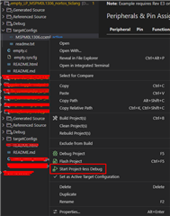
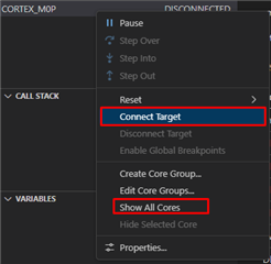
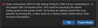
I'm using 8-pin version for space constrains and I need all the available GPIO pins, included SWD pins. I've therefor removed the check of "Debug Enable On SWD Pins" in the sysconfig. When I've programmed the MCU from the CCS with the program command, the programming failed and the chip becomes permanently bricked. I've tried to use factory reset, mass erase, but not possible to connect to the device. But when I connect the reset permanently to GND, it reports different connection error, but no lucky for connection and de-bricking. Has anybody similar experience? And is there some solution for device de-bricking? I have already over 10 pcs bricked. I'm not writing NONMAIN memory, or don't know about it if I do so somehow by mistake.

Used environment: Win11, CCS 20.1.1, latest sysconfig and MSPM0-SDK updates, updated LP-MSPM0C1104 LaunchPad used for programming.

  • Hi Jan,
    Since you disabled the SWD pins, there isn't much you can do to communicate to the device. I have one test I want you to run to see if there core is still accessible. Can you run a Project-less Debug session and see if it's possible to reach the core?

    Best Regards,

    Diego Abad

  • Hello Diego, I'll test it when I'll hit the new brick. I've scratched all the bricked samples during resoldering.

    BTW, I've supposed that even the "Debug" is disabled, the programming is still available as the bootloader is reactivated after the hard reset, which remains still the NRST function on the pin. Is this correct, or not?

  • Hi Jan,
    For the L and G family, BSL invoking is possible. However, the C family doesn't have BSL. I'll have to confirm it with my team, but I'm 90% sure you can't use the NRST pin to enter BSL for this device.
    Best Regards,
    Diego Abad

  • Hi Diego,

    well, how to use the PA19 and PA20 then as a GPIO, PWM output and so on, when I'm not able to disable Debug function? Ideally even PA1 / NRST may be used for application too. But how if I need it for reprogramming? May be that for this pin it is a bit more clear, because I may use software reset instead. But I need to have the SWD working. I guess that SWD is working all the time and can't even be disabled, independently to the Debug function, which I don't need now.

  • Hi Jan,
    A solution for this will be to have a period of time before the project enters the application where you can access the SWD lines. Something as the pseudocode bellow:

    int main(void){

         Wait for x seconds before configuring any pins (time used to program the device if needed)

         SYSCONFIG call

         Device now can't use SWD

    }

    That way, you have a small window of time before your SWD pins stop working. You can also use a software mechanism that activates and deactivates the SWD lines through a PIN (input pin 1 = SWD on / input pin 0 = SWD off.)

    Best Regards,

    Diego Abad

  • Hi Diego,

    I tried to find some more information about the "Debug" and SWD programming pins dependencies in the slau893b.pdf document, but there is nothing about that. Therefor I've expected that these two functions are separated from each other and independent. The wait function, you've mentioned, is normally there as BSL is invoked after NRST reset as written in this document. But there seems to be some issue with the flash erase, because the "Mass erase" function doesn't work and when this erase is invoked, it reports error that this function is not supported for this family. Again, based on the document, it is supported. Mass erase function was working some time ago. There need to be some issue with the Uniflash tool. I remember, that when I've started to play with the demo board, I've uploaded bin file instead of out format and the board was not responding the same way. The solution than was combination of Mass erase first and then factory reset after. It was working every time.

    BTW, based on paragraph 17.4 the debug disable is mandatory for safety reasons, but there is missing some code example for this essential function and combinations of debug disable functions. Please be so kind and provide some sample set.

  • Hi Jan,

    What version of Uniflash are you using? I would recommend to update it just in case there is an issue with an older revision. Also, I agree that Mass Erase and Factory Erase should work on the MSPM0C1104. Have you got a chance to do the core finding I mentioned in my first response?

    I can share some lines of code you can use to disable the SWD lines for programming. 

        /* Set the DISABLE bit in the SWDCFG register in SYSCTL along with KEY */
        SYSCTL->SOCLOCK.SWDCFG = (SYSCTL_SWDCFG_KEY_VALUE | SYSCTL_SWDCFG_DISABLE_TRUE);
    You can also disable this i Sysconfig by unchecking this checkbox.
    Best Regards,
    Diego Abad
  • Hello Diego,

    I'm using MSPM0C1103SDDFR and had the same problem Jan had. I tried your script to do the core finding and it did not work. I get the same response as when I try to flash the MCU.

    Funny thing is, this is not the first time I loaded a firmware with the debug pins configured as GPIOs, but the first time I was able to save the chip. The problem is I do not know exactly what I did to save it. But it involved several attempts to do a factory reset and connecting my NRST pin to GND and then disconnecting it.

    If you think of anything I can try please let me know.

  • Hi Jean and Jan,
    The best advice to "unbrick" this device is to try to reach the SW pins before starting to execute the code in FLASH. However, this time window will be incredibly small, and it will require multiple attempts to accomplish this. I agree that the current best approach is to factory reset script on the device after a reset happens.
    Best Regards,
    Diego Abad

  • Hi Diego and Jean,

    as I've understood, the flash controller is a part of the bootloader and therefor need to be MCU in active mode, not in reset as it is for some other devices to enter the programming mode. Therefor it is not possible to put NRST to GND permanently to disable the firmware start. Then it is really difficult to catch the correct state because there is only very short window before the SYSCFG_DL_init(); is loaded hence it is the first line of the code.

    To make the story short, I'll explain exactly what I need. Due to cyber security reasons I need to disable all the unused pins and debug functions. Unused pins are not a problem hence I have used all of them. I need to disable therefor flash and memory readouts and all debugging functions except the "hard" factory reset and reflash possibility as a emergency last resort. The password protected function is not possible to use.

    Seems that it may be based on the delayed SYSCFG load and combinations of lock functions for Read / Write operations.

    Any idea how to do so safely and correctly?

  • Hello Diego and Jan,

    I forgot to mention something I changed from the first time to the second: I added a small delay before SYSCFG_DL_init() thinking it would make my life easier. Apparently I was wrong, since I saved the chip the first time but not this one. Does it make any sense?

    int main(void)
    {
        delay_cycles(12000000);
        SYSCFG_DL_init();

    Anyway, I'm considering doing what Diego suggested "You can also use a software mechanism that activates and deactivates the SWD lines through a PIN", however the only pin I have left is the NRST pin. So I'm thinking, it wouldn't be possible to start the chip with it on GND as it would still have its NRST function, right? But I can start it as an input and then, during the execution of the code when I receive a 0 in it, I enable the debug functions on SW pins.

    Does it make any sense? Can you share a script of how I can disable the GPIO functions on SW pins and enable the debug functions back?

  • Hi Jean,
    You are correct. You can in theory set a delay or an input to turn on and off the debug lines. To disable/enable you can use the following:

    Disable  ==> SYSCTL->SOCLOCK.SWDCFG = (SYSCTL_SWDCFG_KEY_VALUE | SYSCTL_SWDCFG_DISABLE_TRUE);

    Enable ==>SYSCTL->SOCLOCK.SWDCFG = (SYSCTL_SWDCFG_KEY_VALUE);

    Best Regards,

    Diego Abad

  • Hi Jan,
    You are correct in regards of disabling the SW lines to add mores security to the device. However, we only recommend doing this once the code is finalized and there is no further changes that the user needs to do. Thus, the device works as intended, but it can't be re-programmed again (unless a POR happens and somehow it is able to connect with the SW lines.) The approach of a window of time and/or a pin to activate/deactivate the SW lines is the best approach to toggling SW functionality without "bricking" the device.

    Best Regards,

    Diego Abad

  • Hello Jean and Diego,

    Thank you for your points. Hope I'll be able to implement all into my code with the positive results.

  • Hi Jan,
    Glad to be of help. If you need any other help I recommend creating a new E2E post. 

    Best Regards,

    Diego Abad

  • Hi Jan and Diego,

    I've found a way to unbrick my MCUs and keep them avaliable for programming again. You just need the XDS programmer board (LaunchPad) and Uniflash.

    1. Stick your programmer in your board with Vcc, GND, SWDIO, and SWCLK pins connected, but connect the NRST of your MCU to GND (NRST = '0').
    2. Run the "Factory Reset Manual" script. The software will be able to communicate with your chip and will ask you to press the reset button.
    3. Release your NRST from GND (NRST = '1').
    4. Factory reset will be completed and memory will be erased. Chip is now ready for programming.

    I hope this helps. It works for me even without a delay in the beginning of the code.

    Reference:

    MSPM0C1103: about use together SWIO/CLK and IO PINS - Arm-based microcontrollers forum - Arm-based microcontrollers - TI E2E support forums

  • Hello Jean,

    thank you for your hints, but this method was already tested. It's not working either because the NRST is used as a GPIO and therefor the Reset function is not available. I've even tried to reduce the Vcc down to reach the POR, but then the communication stops completely.

  • Finally I've found the solution which is working for me. It is similar to the Jean's steps, with some specific points. Because I'm using NRST as a GPIO, the regular reset is not available. Therefor I need to use POR instead. The steps are as follows:

    1) Disconnect application Vcc and debugger from USB and wait enough to MCU loose the power below POR threshold.

    2) Disconnect the NRST pin from debugger and connect it directly to GND with wire.

    3) Run the  "Factory Reset Manual" script and when asked to "Press the Reset Button" disconnect the NRST to GND connection. The MCU was reset to factory defaults. The application will respond to close the debug session, but it is not needed.

    4) The MCU memory is cleared and ready for the new firmware upload.

    The steps 1) and 2) are the most critical. In my case I had connected the debugger via the USB all the time and the MCU was powered via the NRST wire which is HIGH all the time, except hard reset short pulse. This pulse is too short to activate the POR in my app.

    Another boot condition is needed - NRST need to be HIGH during POR state, for example pull-up resistor from NRST to Vcc. This is mandatory even the NRST function is disabled and the NRST is used as a open drain output, or input.

  • Hi Jan,

    I'm glad to see you found a solution for this. I'll pin this comment out for any future customer that may need this information.

    Best Regards,

    Diego Abad