This thread has been locked.

If you have a related question, please click the "Ask a related question" button in the top right corner. The newly created question will be automatically linked to this question.

AM2612: ecap for GPIO cannot work

Part Number: AM2612
Other Parts Discussed in Thread: SYSCONFIG, LP-AM261

Tool/software:

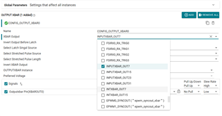
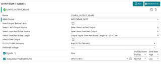
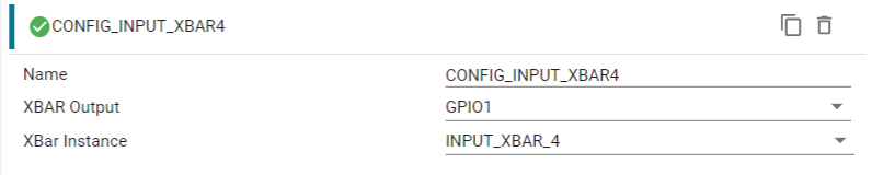
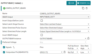
I configured GPIO47 as EPWM2A, and then configured GPIO47 to connect to inputxbar0, and then to ECAP0. I can capture the duty cycle and frequency of EPWM2A through ECAP0.

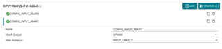
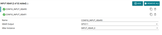
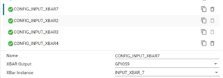
While keeping the EPWM2 and ECAP configurations unchanged, I configured GPIO59 as IO input, and changed the inputxbar0 configuration to connect to GPIO59. I connected GPIO47 and GPIO59 together externally with a wire (GPIO59 can be measured with an oscilloscope), but ECAP cannot capture any events. Why?

  • Additional information: I changed the GPIO and found that GPIOs before GPIO57 can capture the signal using ECAP, while GPIOs after GPIO57 cannot capture the signal, even if I switch to other inputxbar.

  • Hey Zhou,

    Thanks for reaching out regarding your issue. I will be looking into this for you. In the meantime, can you examine and provide the pinmux (IOMUX) configuration for GPIO47 when the ecap correctly captures the PWM and the same info for GPIO59 where it is incorrectly captured?

    My thought is that maybe GPIO59 input buffer isn't configured to recieve the signal from GPIO47.

    You are configuring INPUTXBAR[0] the exact same for both cases?

    Best Regards,

    Zackary Fleenor

  • Hi Fleenor,

    Thank you for your explanation. 

    I need to provide some additional information: I made minor modifications to the eCAP example [ecap_capture_epwm], using SDK 10.0.1.10 and SysConfig 1.22.0. Then, I determined whether the signal was captured by monitoring the DebugP_log information and the value of the EVENT register in the eCAP registers.

    Regarding the two issues you mentioned, I have checked the settings:

    I only modified the SysConfig configuration, regenerated the code, and made no other changes except to resolve the error.

    When the eCAP correctly captures the GPIO47 signal from EPWM2, the configuration is as follows:

    • IOMUX_GPIO47_CFG_REG = 0x01000500 (HVMODE_STATUS & SC1 & PE = 1, others = 0)
    • IOMUX_GPIO59_CFG_REG = 0x00000507 (C1 & PE & FCNC_SEL = 1, others = 0)

    However, when an external connection wire is used to link GPIO47 and GPIO59 (connecting LaunchPad’s [J4 31-PIN to 40-PIN]), the signal cannot be captured. The configuration remains:

    • IOMUX_GPIO47_CFG_REG = 0x01000500
    • IOMUX_GPIO59_CFG_REG = 0x00000507 

    Regarding the INPUT XBAR configuration, I only modified the setting in SysConfig: INPUT XBAR -> XBAR Output from GPIO47 to GPIO59.

    In the code, the only difference is this line:

    SOC_xbarSelectInputXBarInputSource_ext(CSL_CONTROLSS_INPUTXBAR_U_BASE, 0, 0, INPUT_XBAR_GPIO47, 0, 0);
    SOC_xbarSelectInputXBarInputSource_ext(CSL_CONTROLSS_INPUTXBAR_U_BASE, 0, 0, INPUT_XBAR_GPIO47, 0, 0);
     
  • I apologize for the error in the last line. It should be:

    SOC_xbarSelectInputXBarInputSource_ext(CSL_CONTROLSS_INPUTXBAR_U_BASE, 0, 0, INPUT_XBAR_GPIO59, 0, 0);

  • Hey Zhou,

    Thanks for providing these details. Can you share the .syscfg file here for review?

    Can you try manually configuring IOMUX_GPIO59_CFG_REG to match the working GPIO47 configuration?

    Is there any possibility that GPIO59 is already being configured/utlized by another compontent in the system?

    What is the HVMODE_STATUS you mentioned?

    Best Regards,

    Zackary Fleenor

  • Hi Fleenor,

    Thank you for your explanation. About your questions:

    1. I tried to upload the sysconfig file, but it failed. I will provide the sysconfig code below to see if that works.

    2. I tried configuring GPIO59 to the same mode as GPIO47, but it didn’t work. In my code, I set HVMODE_STATUS to 1, but I found that this bit in the register is read-only and cannot be modified. The other bits can be configured to match GPIO47. However, even after this configuration, the eCap still cannot capture the output waveform.

    3. I don’t think it’s likely that GPIO59 is being used by other components in the system, because my project’s hardware design is set up to use GPIO59 to capture a specific waveform, but my code isn’t working. Therefore, I chose to use the launchpad and modify the example code.

    4. HVMODE_STATUS is bit 24 in the IOMUX_GPIO57_CFG_REG register.
    Bit: 24
    Field: HVMODE_STATUS
    Type: R
    Reset: 0h
    Description: IO Power group indication 0: 1.8V Power Domain 1: 3.3V Power Domain


    I would like to ask if the 1.8V and 3.3V setting of this bit can affect whether GPIO59 can be used as an eCap to capture a waveform. Or, alternatively, Could you provide a simple example routine for configuring GPIO59 as an IO input for eCap capture input? If it runs successfully, I can then compare the registers or modify it to adapt to my program. Thank you.

    Best regards.

    -----------------------------------Here is the code for the sysconfig file.------------------------------------------------

    /**
     * These arguments were used when this file was generated. They will be automatically applied on subsequent loads
     * via the GUI or CLI. Run CLI with '--help' for additional information on how to override these arguments.
     * @cliArgs --device "AM261x_ZFG" --part "AM2612" --package "ZFG" --context "r5fss0-0" --product "MCU_PLUS_SDK_AM261x@10.00.01"
     * @v2CliArgs --device "AM2612" --package "NFBGA (ZFG)" --context "r5fss0-0" --product "MCU_PLUS_SDK_AM261x@10.00.01"
     * @versions {"tool":"1.22.0+3893"}
     */
    
    /**
     * Import the modules used in this configuration.
     */
    const ecap            = scripting.addModule("/drivers/ecap/ecap", {}, false);
    const ecap1           = ecap.addInstance();
    const epwm            = scripting.addModule("/drivers/epwm/epwm", {}, false);
    const epwm1           = epwm.addInstance();
    const gpio            = scripting.addModule("/drivers/gpio/gpio", {}, false);
    const gpio1           = gpio.addInstance();
    const dpl_cfg         = scripting.addModule("/kernel/dpl/dpl_cfg");
    const mpu_armv7       = scripting.addModule("/kernel/dpl/mpu_armv7", {}, false);
    const mpu_armv71      = mpu_armv7.addInstance();
    const mpu_armv72      = mpu_armv7.addInstance();
    const mpu_armv73      = mpu_armv7.addInstance();
    const mpu_armv74      = mpu_armv7.addInstance();
    const default_linker  = scripting.addModule("/memory_configurator/default_linker", {}, false);
    const default_linker1 = default_linker.addInstance();
    const general         = scripting.addModule("/memory_configurator/general", {}, false);
    const general1        = general.addInstance();
    const region          = scripting.addModule("/memory_configurator/region", {}, false);
    const region1         = region.addInstance();
    const section         = scripting.addModule("/memory_configurator/section", {}, false);
    const section1        = section.addInstance();
    const section2        = section.addInstance();
    const section3        = section.addInstance();
    const section4        = section.addInstance();
    const section5        = section.addInstance();
    const section6        = section.addInstance();
    const section7        = section.addInstance();
    const section8        = section.addInstance();
    const section9        = section.addInstance();
    const section10       = section.addInstance();
    const section11       = section.addInstance();
    const section12       = section.addInstance();
    const input_xbar      = scripting.addModule("/xbar/input_xbar/input_xbar", {}, false);
    const input_xbar1     = input_xbar.addInstance();
    const int_xbar        = scripting.addModule("/xbar/int_xbar/int_xbar", {}, false);
    const int_xbar1       = int_xbar.addInstance();
    
    /**
     * Write custom configuration values to the imported modules.
     */
    ecap1.$name                  = "CONFIG_ECAP0";
    ecap1.enableInterrupt        = true;
    ecap1.interruptSourceAPWM    = ["ECAP_ISR_SOURCE_COUNTER_PERIOD"];
    ecap1.captureMode            = "ECAP_ONE_SHOT_CAPTURE_MODE";
    ecap1.eventStop              = "ECAP_EVENT_4";
    ecap1.eventOnePolarity       = "ECAP_EVNT_FALLING_EDGE";
    ecap1.eventThreePolarity     = "ECAP_EVNT_FALLING_EDGE";
    ecap1.interruptSourceCapture = ["ECAP_ISR_SOURCE_CAPTURE_EVENT_4"];
    ecap1.counterResetOnEvent    = ["ECAP_EVENT_1","ECAP_EVENT_2","ECAP_EVENT_3","ECAP_EVENT_4"];
    ecap1.reArm                  = true;
    ecap1.enableLoadCounter      = true;
    ecap1.ecapInput              = "ECAP_INPUT_INPUTXBAR0";
    
    epwm1.epwmTimebase_counterMode                                = "EPWM_COUNTER_MODE_UP";
    epwm1.epwmTimebase_period                                     = 500;
    epwm1.epwmTimebase_hsClockDiv                                 = "EPWM_HSCLOCK_DIVIDER_2";
    epwm1.epwmActionQualifier_EPWM_AQ_OUTPUT_A_ON_TIMEBASE_PERIOD = "EPWM_AQ_OUTPUT_TOGGLE";
    epwm1.$name                                                   = "CONFIG_EPWM2";
    epwm1.EPWM.$assign                                            = "EPWM2";
    epwm1.EPWM.A.$assignAllowConflicts                            = "GPIO47";
    epwm1.EPWM.B.$assign                                          = "GPIO48";
    
    gpio1.$name          = "CONFIG_INPUT";
    gpio1.GPIO_n.$assign = "GPIO59";
    
    const soc_ctrl_adc    = scripting.addModule("/drivers/soc_ctrl/v0/subModules/soc_ctrl_adc", {}, false);
    const soc_ctrl_adc1   = soc_ctrl_adc.addInstance({}, false);
    soc_ctrl_adc1.$name   = "soc_ctrl_adc0";
    const soc_ctrl        = scripting.addModule("/drivers/soc_ctrl/soc_ctrl", {}, false);
    soc_ctrl.soc_ctrl_adc = soc_ctrl_adc1;
    
    const soc_ctrl_cmpss    = scripting.addModule("/drivers/soc_ctrl/v0/subModules/soc_ctrl_cmpss", {}, false);
    const soc_ctrl_cmpss1   = soc_ctrl_cmpss.addInstance({}, false);
    soc_ctrl_cmpss1.$name   = "soc_ctrl_cmpss0";
    soc_ctrl.soc_ctrl_cmpss = soc_ctrl_cmpss1;
    
    const soc_ctrl_epwm    = scripting.addModule("/drivers/soc_ctrl/v0/subModules/soc_ctrl_epwm", {}, false);
    const soc_ctrl_epwm1   = soc_ctrl_epwm.addInstance({}, false);
    soc_ctrl_epwm1.$name   = "soc_ctrl_epwm0";
    epwm.epwmTbClkSync     = soc_ctrl_epwm1;
    soc_ctrl.soc_ctrl_epwm = soc_ctrl_epwm1;
    
    const soc_ctrl_sdfm    = scripting.addModule("/drivers/soc_ctrl/v0/subModules/soc_ctrl_sdfm", {}, false);
    const soc_ctrl_sdfm1   = soc_ctrl_sdfm.addInstance({}, false);
    soc_ctrl_sdfm1.$name   = "soc_ctrl_sdfm0";
    soc_ctrl.soc_ctrl_sdfm = soc_ctrl_sdfm1;
    
    mpu_armv71.$name             = "CONFIG_MPU_REGION0";
    mpu_armv71.size              = 31;
    mpu_armv71.attributes        = "Device";
    mpu_armv71.accessPermissions = "Supervisor RD+WR, User RD";
    mpu_armv71.allowExecute      = false;
    
    mpu_armv72.$name             = "CONFIG_MPU_REGION1";
    mpu_armv72.size              = 15;
    mpu_armv72.accessPermissions = "Supervisor RD+WR, User RD";
    
    mpu_armv73.$name             = "CONFIG_MPU_REGION2";
    mpu_armv73.baseAddr          = 0x80000;
    mpu_armv73.size              = 15;
    mpu_armv73.accessPermissions = "Supervisor RD+WR, User RD";
    
    mpu_armv74.$name             = "CONFIG_MPU_REGION3";
    mpu_armv74.accessPermissions = "Supervisor RD+WR, User RD";
    mpu_armv74.baseAddr          = 0x70000000;
    mpu_armv74.size              = 21;
    
    default_linker1.$name = "memory_configurator_default_linker0";
    
    general1.$name        = "CONFIG_GENERAL0";
    general1.linker.$name = "TIARMCLANG0";
    
    region1.$name                                = "MEMORY_REGION_CONFIGURATION0";
    region1.memory_region.create(11);
    region1.memory_region[0].type                = "TCMA";
    region1.memory_region[0].$name               = "R5F_VECS";
    region1.memory_region[0].size                = 0x40;
    region1.memory_region[0].auto                = false;
    region1.memory_region[1].type                = "TCMA";
    region1.memory_region[1].$name               = "R5F_TCMA";
    region1.memory_region[1].size                = 0x7FC0;
    region1.memory_region[2].type                = "TCMB";
    region1.memory_region[2].size                = 0x8000;
    region1.memory_region[2].$name               = "R5F_TCMB";
    region1.memory_region[3].$name               = "SBL";
    region1.memory_region[3].auto                = false;
    region1.memory_region[3].size                = 0x40000;
    region1.memory_region[4].$name               = "OCRAM";
    region1.memory_region[4].auto                = false;
    region1.memory_region[4].manualStartAddress  = 0x70040000;
    region1.memory_region[4].size                = 0x40000;
    region1.memory_region[5].type                = "FLASH";
    region1.memory_region[5].auto                = false;
    region1.memory_region[5].manualStartAddress  = 0x60100000;
    region1.memory_region[5].size                = 0x80000;
    region1.memory_region[5].$name               = "FLASH";
    region1.memory_region[6].$name               = "USER_SHM_MEM";
    region1.memory_region[6].auto                = false;
    region1.memory_region[6].manualStartAddress  = 0x70150000;
    region1.memory_region[6].size                = 0x4000;
    region1.memory_region[6].isShared            = true;
    region1.memory_region[6].shared_cores        = ["r5fss0-1"];
    region1.memory_region[7].$name               = "LOG_SHM_MEM";
    region1.memory_region[7].auto                = false;
    region1.memory_region[7].manualStartAddress  = 0x70154000;
    region1.memory_region[7].size                = 0x4000;
    region1.memory_region[7].isShared            = true;
    region1.memory_region[7].shared_cores        = ["r5fss0-1"];
    region1.memory_region[8].type                = "CUSTOM";
    region1.memory_region[8].$name               = "RTOS_NORTOS_IPC_SHM_MEM";
    region1.memory_region[8].auto                = false;
    region1.memory_region[8].manualStartAddress  = 0x72000000;
    region1.memory_region[8].size                = 0x3E80;
    region1.memory_region[8].isShared            = true;
    region1.memory_region[8].shared_cores        = ["r5fss0-1"];
    region1.memory_region[9].type                = "CUSTOM";
    region1.memory_region[9].$name               = "MAILBOX_HSM";
    region1.memory_region[9].auto                = false;
    region1.memory_region[9].manualStartAddress  = 0x44000000;
    region1.memory_region[9].size                = 0x3CE;
    region1.memory_region[9].isShared            = true;
    region1.memory_region[9].shared_cores        = ["r5fss0-1"];
    region1.memory_region[10].type               = "CUSTOM";
    region1.memory_region[10].$name              = "MAILBOX_R5F";
    region1.memory_region[10].auto               = false;
    region1.memory_region[10].manualStartAddress = 0x44000400;
    region1.memory_region[10].size               = 0x3CE;
    region1.memory_region[10].isShared           = true;
    region1.memory_region[10].shared_cores       = ["r5fss0-1"];
    
    section1.load_memory                  = "R5F_VECS";
    section1.group                        = false;
    section1.$name                        = "Vector Table";
    section1.output_section.create(1);
    section1.output_section[0].$name      = ".vectors";
    section1.output_section[0].palignment = true;
    
    section2.load_memory                  = "OCRAM";
    section2.$name                        = "Text Segments";
    section2.output_section.create(5);
    section2.output_section[0].$name      = ".text.hwi";
    section2.output_section[0].palignment = true;
    section2.output_section[1].$name      = ".text.cache";
    section2.output_section[1].palignment = true;
    section2.output_section[2].$name      = ".text.mpu";
    section2.output_section[2].palignment = true;
    section2.output_section[3].$name      = ".text.boot";
    section2.output_section[3].palignment = true;
    section2.output_section[4].$name      = ".text:abort";
    section2.output_section[4].palignment = true;
    
    section3.load_memory                  = "OCRAM";
    section3.$name                        = "Code and Read-Only Data";
    section3.output_section.create(2);
    section3.output_section[0].$name      = ".text";
    section3.output_section[0].palignment = true;
    section3.output_section[1].$name      = ".rodata";
    section3.output_section[1].palignment = true;
    
    section4.load_memory                  = "OCRAM";
    section4.$name                        = "Data Segment";
    section4.output_section.create(1);
    section4.output_section[0].$name      = ".data";
    section4.output_section[0].palignment = true;
    
    section5.load_memory                             = "OCRAM";
    section5.$name                                   = "Memory Segments";
    section5.output_section.create(3);
    section5.output_section[0].$name                 = ".bss";
    section5.output_section[0].output_sections_start = "__BSS_START";
    section5.output_section[0].output_sections_end   = "__BSS_END";
    section5.output_section[0].palignment            = true;
    section5.output_section[1].$name                 = ".sysmem";
    section5.output_section[1].palignment            = true;
    section5.output_section[2].$name                 = ".stack";
    section5.output_section[2].palignment            = true;
    
    section6.load_memory                              = "OCRAM";
    section6.$name                                    = "Stack Segments";
    section6.output_section.create(5);
    section6.output_section[0].$name                  = ".irqstack";
    section6.output_section[0].output_sections_start  = "__IRQ_STACK_START";
    section6.output_section[0].output_sections_end    = "__IRQ_STACK_END";
    section6.output_section[0].input_section.create(1);
    section6.output_section[0].input_section[0].$name = ". = . + __IRQ_STACK_SIZE;";
    section6.output_section[1].$name                  = ".fiqstack";
    section6.output_section[1].output_sections_start  = "__FIQ_STACK_START";
    section6.output_section[1].output_sections_end    = "__FIQ_STACK_END";
    section6.output_section[1].input_section.create(1);
    section6.output_section[1].input_section[0].$name = ". = . + __FIQ_STACK_SIZE;";
    section6.output_section[2].$name                  = ".svcstack";
    section6.output_section[2].output_sections_start  = "__SVC_STACK_START";
    section6.output_section[2].output_sections_end    = "__SVC_STACK_END";
    section6.output_section[2].input_section.create(1);
    section6.output_section[2].input_section[0].$name = ". = . + __SVC_STACK_SIZE;";
    section6.output_section[3].$name                  = ".abortstack";
    section6.output_section[3].output_sections_start  = "__ABORT_STACK_START";
    section6.output_section[3].output_sections_end    = "__ABORT_STACK_END";
    section6.output_section[3].input_section.create(1);
    section6.output_section[3].input_section[0].$name = ". = . + __ABORT_STACK_SIZE;";
    section6.output_section[4].$name                  = ".undefinedstack";
    section6.output_section[4].output_sections_start  = "__UNDEFINED_STACK_START";
    section6.output_section[4].output_sections_end    = "__UNDEFINED_STACK_END";
    section6.output_section[4].input_section.create(1);
    section6.output_section[4].input_section[0].$name = ". = . + __UNDEFINED_STACK_SIZE;";
    
    section7.load_memory                  = "OCRAM";
    section7.$name                        = "Initialization and Exception Handling";
    section7.output_section.create(3);
    section7.output_section[0].$name      = ".ARM.exidx";
    section7.output_section[0].palignment = true;
    section7.output_section[1].$name      = ".init_array";
    section7.output_section[1].palignment = true;
    section7.output_section[2].$name      = ".fini_array";
    section7.output_section[2].palignment = true;
    
    section8.load_memory                 = "USER_SHM_MEM";
    section8.type                        = "NOLOAD";
    section8.$name                       = "User Shared Memory";
    section8.group                       = false;
    section8.output_section.create(1);
    section8.output_section[0].$name     = ".bss.user_shared_mem";
    section8.output_section[0].alignment = 0;
    
    section9.load_memory                 = "LOG_SHM_MEM";
    section9.$name                       = "Log Shared Memory";
    section9.group                       = false;
    section9.type                        = "NOLOAD";
    section9.output_section.create(1);
    section9.output_section[0].$name     = ".bss.log_shared_mem";
    section9.output_section[0].alignment = 0;
    
    section10.load_memory                 = "RTOS_NORTOS_IPC_SHM_MEM";
    section10.type                        = "NOLOAD";
    section10.$name                       = "IPC Shared Memory";
    section10.group                       = false;
    section10.output_section.create(1);
    section10.output_section[0].$name     = ".bss.ipc_vring_mem";
    section10.output_section[0].alignment = 0;
    
    section11.load_memory                 = "MAILBOX_HSM";
    section11.type                        = "NOLOAD";
    section11.$name                       = "SIPC HSM Queue Memory";
    section11.group                       = false;
    section11.output_section.create(1);
    section11.output_section[0].$name     = ".bss.sipc_hsm_queue_mem";
    section11.output_section[0].alignment = 0;
    
    section12.load_memory                 = "MAILBOX_R5F";
    section12.$name                       = "SIPC R5F Queue Memory";
    section12.group                       = false;
    section12.type                        = "NOLOAD";
    section12.output_section.create(1);
    section12.output_section[0].$name     = ".bss.sipc_secure_host_queue_mem";
    section12.output_section[0].alignment = 0;
    
    input_xbar1.$name      = "CONFIG_INPUT_XBAR0";
    input_xbar1.xbarOutput = "GPIO59";
    
    int_xbar1.$name      = "CONFIG_INT_XBAR0";
    int_xbar1.xbarOutput = ["ECAP0_INT"];
    int_xbar1.instance   = "INT_XBAR_22";
    

  • Hi Zhou,

    Thank you for providing this additional information. I do believe that the HVMODE_STATUS bit being set to 0 (1.8V) instead of 1 (3.3V) is playing a role here, based on these settings GPIO59 is expecting a 1.8V magnitude signal and a 3.3V magnitude signal is being applied.

    Are you using either of the OSPI interfaces for your testing? 

    GPIO59 hosts the OSPI[0:1]_D0 pin which explains why it is using 1.8V.

    Would it be possible to use a different GPIO pin (GPIO63?) and implement the same test?

    I am going to loop in a fellow software expert to provide feedback on possibly providing an example for this functionality.

    Please allow some time for them to review.

    Best Regards,

    Zackary Fleenor

  • Hi Zhou

    Additional information: I changed the GPIO and found that GPIOs before GPIO57 can capture the signal using ECAP, while GPIOs after GPIO57 cannot capture the signal, even if I switch to other inputxbar.

    When using GPIO11 connected to GPIO47 through jumper wires, the example is working:

     GPIO Val is read.

    But it is not working for GPIO 59, 74 etc. which validates your hypothesis.

    However, may I ask why not capture EPWM2_A directly through inputxbar, why go through this routing? Also if you need to route through some pin, you can check the outputxbar as well and route through one of those pins.

    Regards,
    Akshit

  • Hi Akshit,

          Thanks for your test. My ultimate goal is to use GPIO59 to capture an external PWM signal, as determined by my PCB design. Therefore, it needs to be configured to capture signals. Using EPWM2A with external wiring is just a simplified routing method for testing purposes. So, why can’t GPIO59 (and, as my tests show, some of the later GPIOs) capture external signals by connecting to inputxbar and connecting to ecap? The manual does not mention any related issues.

    Best regards

  • Hi Fleenor, 

        Thanks for your help. I tested with GPIO63 and the results are as expected. The 1.8V pin configured as eCap cannot capture the waveform. I found that previously, I used OSPI to implement a button display function for a certain HMI, and one of the HMI buttons always did not work. The reason was that the high-level voltage of the HMI GPIO was not 3.3V but 1.8V. So, is the only peripheral affected by the 1.8V IO the eCap? I couldn’t find any relevant description in the manual…

    Best regards

  • Hi Zhou,

    Got it! Could you try using the outputxbar to reroute the signal to one of the pins before gpio57 like:

    Choose one of the available Inputxbars to output using the output xbar:

    output pin is GPIO_11 here:

    set inputxbar_7 to GPIO_59:

    and inputxbar_0 to GPIO_11:

    Capture inputxbar_0 on eqep now!

    Let me know if this works!

    Regards,
    Akshit

  • Hi Akshit,

        In my project, GPIO11 is used as the encoder SCI. Therefore, in the demo program, I tried using GPIO1. I connected GPIO1 to INPUTXBAR4, and ECAP input is set to INPUTXBAR4. At the same time, GPIO1 is the pin for OUTPUTXBAR0, and OUTPUTXBAR0 is connected to INPUTXBAR7. Finally, INPUTXBAR7 is connected to GPIO59. GPIO47 remains as EPWM2A, serving as a hypothetical external output. I connected GPIO47 to GPIO1 externally using a wire, and internally, GPIO1 and GPIO59 are connected through the XBAR. However, the ECAP still hasn’t captured any events. Could it be that my configuration is incorrect(I couldn’t find the configuration in the sysconfig-generated code that designates GPIO1 as an output XBAR)? 

    #define INPUTXBAR_BASE_ADDR             (CSL_CONTROLSS_INPUTXBAR_U_BASE)
    #define OUTPUTXBAR_BASE_ADDR            (CSL_CONTROLSS_OUTPUTXBAR_U_BASE)
    
    void ConfigEcapXbar(void)
    {
        /* OUTPUT XBAR */
        SOC_xbarSelectOutputXBarInputSource(OUTPUTXBAR_BASE_ADDR, 0, 0, 0, 0, 0, 0, 0, 0, 0, 0, ( OUTPUT_XBAR_INPUTXBAR_OUT7  ), 0);
        SOC_xbarInvertOutputXBarOutputSignalBeforeLatch(OUTPUTXBAR_BASE_ADDR, 0);
        SOC_xbarInvertOutputXBarOutputSignal(OUTPUTXBAR_BASE_ADDR, 0);
        SOC_xbarSelectLatchOutputXBarOutputSignal(OUTPUTXBAR_BASE_ADDR, 0);
        SOC_xbarSelectStretchedPulseOutputXBarOutputSignal(OUTPUTXBAR_BASE_ADDR, 0);
        SOC_xbarSelectStretchedPulseLengthOutputXBarOutputSignal(OUTPUTXBAR_BASE_ADDR, 0);
        /* Input XBAR configuration */
        SOC_xbarSelectInputXBarInputSource(INPUTXBAR_BASE_ADDR, 7, 0, INPUT_XBAR_GPIO59, 0); //configure GPIO59 to XBAR7
        SOC_xbarSelectInputXBarInputSource(INPUTXBAR_BASE_ADDR, 4, 0, INPUT_XBAR_GPIO1, 0); //configure GPIO1 to XBAR4
        /* Interrupt XBAR configuration */
        SOC_xbarSelectInterruptXBarInputSource_ext(CSL_CONTROLSS_INTXBAR_U_BASE, 0, 0, 0, 0, 0, 0, ( INT_XBAR_ECAP0_INT ), 0, 0, 0, 0);
        SOC_xbarSelectInterruptXBarInputSource_ext(CSL_CONTROLSS_INTXBAR_U_BASE, 2, 0, 0, 0, 0, 0, ( INT_XBAR_ECAP3_INT ), 0, 0, 0, 0);
    }

    Can you provide an example routine that can use GPIO59 to capture external signals? Here is my configuration reference, thank you.

    best regards.

  • Hi Zhou

    Your configuration is correct, the issue here is:

    The inputxbar for gpio59, is actually giving out always high signal, as can be seen from the outputxbar. Thus the ecap example is failing.

    The same code when ran with gpio52 instead of gpio59:

    Actually gives us the correct output, which is why the ecap example is passing for this pin.

    This does look like a voltage issue, where the low voltage is also being qualified as high, we'll need to confirm this and see how this can be fixed, let me get back to you tomorrow with an update on this.

    Thanks & regards
    Akshit

  • Hi Zhou

    Here's an update I got for you!

    The MCU in LP-AM261 is always made to be 1.8V. This is because these GPIOs come in the same bank as the OSPI IOs and since OSPIs use 1.8V flash, it is fixed at 1.8V IO voltage. No we cannot switch to 3.3V IO voltage on LP-AM261

    it depends on what voltage you have connected on VDDSHV_D and VDDSHV_E.
    If you have connected 1.8V to these, then yes you would have to level shift to 1.8V
    If you have connected 3.3V, then you can just connect external 3.3V PWM

    In LP-AM261 you cannot connect 3.3V on J5 and P16. But yes on the your custom PCB or any other board if we have a provision to change from 1,8V to 3.3V on J5 and P16, then yes all these IOs will work at 3.3V.

    Let me know if this helps!

    Best regards
    Akshit

  • Hi Akshit,

        Thank you for your reply. After going through these steps, I now understand the whole situation. In the future, I will make some adjustments to the hardware. Thank you.

    Best regards.