Part Number: *****>
This thread has been locked.
If you have a related question, please click the "Ask a related question" button in the top right corner. The newly created question will be automatically linked to this question.
Tried to load customer_secure_sample_image and got this error:
CORTEX_M0P: Unable to determine target status after 20 attempts CORTEX_M0P: Failed to remove the debug state from the target before disconnecting. There may still be breakpoint op-codes embedded in program memory. It is recommended that you reset the emulator before you connect and reload your program before you continue debugging
Then tried to load the program which was loaded and run successfully before and got this error:
CORTEX_M0P: Error connecting to the target: (Error -614 @ 0x0) The target indicates there is an error condition from a previous SWD request. Clear the error the condition, and try the SWD request again. (Emulation package 20.0.0.3178)
What might cause these errors?
Thanks!
Crane
Hi Crane,
1. Since the bank swap is used, CSC should also be written in the flash bank 1 at 0x40000, right?
Yes.
If yes, it seems being directly called from reset handler without need to go through CSC any more and it doesn't have the image header.
Yes. This image example is jumped from CSC example after it get verified. And it does not have header within the project. After the project get build, the CCS will attach a image tailer with image version, signature, hash information after the image by a python script.
As for the error you meet, you could not directly run this image example, since it it build with start address 0x4800. And the program will always start with 0x0000, so you need the CSC be placed at boot to jump to the image. When you get MCU locked, you could follow the guidance in 6.1 Unlock MCU of MSPM0 MCUs Development Guide (Rev. F)
Best Regards,
Pengfei
Thanks Pengfei for your support!
Can you help confirm the below statements to see if my understanding is correct?
This means that 4 images need to be built:
1. CSC at 0x00000
2. CSC at 0x40000
3. application image at 0x4800, header will be generated and put together with the image
4. application image at 0x44800, header will be generated and put together with the image
CSC should be able to be programed and start right after being programed while the application can only be programmed and can NOT run right after being programmed.
And in this way the example of customer_secure_code and customer_secure_sample_image can run properly, right?
And programing customer_secure_code (CSC) needs to erase non-main first as it needs to write data to this section in flash, right? Then a Factory Reset would be needed every time when programming a updated CSC, right?
And when programing customer_secure_sample_image, I get below issues. What might be the cause?
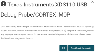
But when programming customer_secure_sample_image .out file to flash, it doesn't work on CCS and works on UniFlash. But after being programed successfully to flash on UniFlash, the memory can't be read back to be verified on UniFlash. The error is as below:
Thanks!
Crane
CSC should be able to be programed and start right after being programed while the application can only be programmed and can NOT run right after being programmed.
Yes. But if CSC program is run without the application program exist in corresponding flash address, the CSC will could not pass the image verification and stall in the CSC program itself.
And programing customer_secure_code (CSC) needs to erase non-main first as it needs to write data to this section in flash, right? Then a Factory Reset would be needed every time when programming a updated CSC, right?
Yes, you are correct.
For the problem you meet, it may caused by: after you program the CSC sample image program to MCU, the program will auto start with 0x0000 address and find no program in this address, so some error pop up. I could apply my private relation ship and I could send you a guidance about how to test with these examples.
Ok good. Thanks Pengfei for confirming these.
I am kind of scared of the warning about erasing non-main memory possibly bricking the MCU as I have only one board in my hand and the board is not available in Canada yet. I try to understand fully what kind of mistakes when erasing non-main memory could brick the MCU so that I can try to avoid all these. I get that losing power in the middle, interrupted erasing process, modifying it incorrectly and erasing it without programming could cause this result.
Then my questions are: Isn't the command of Factory Reset just to erase the non-main memory without programming it? What does modifying it incorrectly specifically refers to? And anything else that could brick the MCU that I might miss?
To clarify, the error in the last post occurs when reading back the flash after programing the application (try to read back to verify it is programmed correctly).
Anyway, the friend request is sent.
Regards,
Crane
Hi Crane,
Then my questions are: Isn't the command of Factory Reset just to erase the non-main memory without programming it? What does modifying it incorrectly specifically refers to? And anything else that could brick the MCU that I might miss?
The Factory Reset will erase the NONMAIN memory and then write the default value to it. Actually you could see 1.6 NONMAIN_G351x_G151x Registers MSPM0 G-Series 80-MHz Microcontrollers Technical Reference Manual (Rev. B) for all the NONMAIN definition of MSPM0G3519. The content in it will be used in boot stage of MCU, and if the information in it is not configured correctly, the MCU may boot fail and could not go to the main flash program.