Part Number: AM263P4
Tool/software:
Hi.
I am considering AM263P4. This device has 4 cores. I have never used a multi-core microcontroller.
Is it possible to control each core separately?
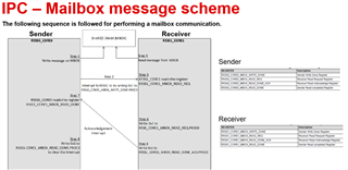
If the answer to the above question is yes, Is it possible to exchange data using memory in each core?
For exsample, CPU0⇔CPU1, CPU0⇔CPU2, CPU0⇔CPU3, CPU0⇔CPU4, CPU1⇔CPU2, CPU1⇔CPU3, CPU1⇔CPU4, CPU2⇔CPU3, CPU2⇔CPU4, CPU3⇔CPU4.
Best regards.