This thread has been locked.

If you have a related question, please click the "Ask a related question" button in the top right corner. The newly created question will be automatically linked to this question.

AM2634: SDFM EPWM sync CPU read example issues

Part Number: AM2634
Other Parts Discussed in Thread: TMDSCNCD263, AMC1306EVM

Tool/software:

Hi all!

I am trying to run the SDFM EPWM sync CPU read example on my tmdscncd263 control card.

https://dev.ti.com/tirex/content/mcu_plus_sdk_am263x_10_01_00_31/docs/api_guide_am263x/EXAMPLES_DRIVERS_SDFM_EPWM_SYNC_CPUREAD.html 

Running CCS Version 20.1.1 (20.1.1.466), MCU SDK - mcu_plus_sdk_am263x_10_01_00_31. I am running the imported project without modification.

https://github.com/TexasInstruments/mcupsdk-core/blob/next/examples/drivers/sdfm/sdfm_epwm_sync_cpuread/sdfm_epwm_sync_cpuread.c#L65 

I have a single AMC1306EVM I am powering and sourcing to D0. I have confirmed this IC is working as I can see DOUT output a digital signature when using the PWM waveform as a clk source (see below).

I have 3 problems on this project:

  1. Where I am seeing DebugP_log messages in CIO from other imported projects, I am not seeing them from running this project.
    1. I can see some DebugP_log when running `screen` locally, but i never see the startup messages
      1. DebugP_log("SDFM EPWM Sync CPU Read Test Started ...\r\n");
        DebugP_log("Please wait %d seconds ...\r\n", APP_RUN_TIME);
    2. I do see the following from `screen
      1. SDFM ISR count: 0
        Modulator failure
      2. (repeat)
  2. When attaching a scope to HSEC Pin 72 (SDFM0_CLK0), I don't see any waveform.
    1. It does not seem like the clock is correctly enabled in the example code.
    2. I do need the output clk working, I cannot rely on a PWM output as the clk source.
  3. If I plug the ePWM HSEC Pin 51 output into my SDFM AMC1306EVM as the clock source, I do see the SDFM IC output a digital signature on DOUT.
    1. But the Sitara does not seem to receive the D0 data result or process it.
    2. The sdfmISR1 function does not seem to ever trigger (confirmed by using a breakpoint during debugging).
      1. Is this a result of the int_xbar not configured?

And a quick observation

  • The clock sources for SDFM_FILTER_2, 3, 4 are configured but it does not look like 1 is. Is this done on purpose? If so why?
  • Note, I have added a line configuring SDFM_FILTER_1 and it does not solve my issues above.
  • github.com/.../sdfm_epwm_sync_cpuread.c

Any help is appreciated! This topic is required ASAP for my use case. If some expert wouldn't mind reviewing or rerunning the example code that would be incredible.

Thank you kindly!

  • Hey Justin,

    I have looped in a fellow software expert to review your issue and the SDFM example implementation. Please allow some time for them to review and provide feedback.

    Best Regards,

    Zackary Fleenor

  • Hi Justin,

    1. The SDFM0_CLK0 is not an output pin, rather an input pin, to which you have to feed the clock, this solves your Modulator failure issue.
    2. DebugP_log, see syscfg if the DebanP_log is enabled for both uart as well as ccs logs. you would see the console logs for ccs logs enabled and terminal logs for uart log enabled.
    3. The interrupt not firing could be because of the clock not present. 

    Please try these and let me know! 

    thanks and regards,

    Madhava

  • Hi Madhava,

    Thank you for your response. After understanding SDFM0_CLK0 is a clock input, we reviewed all the SDFM documentation and the lab diagrams and have a better understanding of the peripheral.

    Also the example.syscfg from the lab did not have Debug Log -> Enable CCS Log configured. After configuring it, I do see console messages. Thanks!

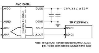
    We also understand now the SDFM IC EVM we have, the AMC1306, requires an input clock. Where its counterpart, AMC1303 has a clock output.


    Again, we are using the AMC1306 EVM today. Today, we are only using a single AMC1306 instead of 4 as the example asks.

    When I run the example code and provide HSEC Pin 51 (Clock generated by EPWM0_B) to the ACM1306 CLKIN, I do see DOUT produce a digital waveform, confirmed on a scope.

    As the diagram above describes, I expect I should connect EPWM0_B to AMC1306-CLKIN and SDFM0_CLK0 on the Sitara. When connecting HSEC Pin 51 (Clock generated by EPWM0_B) to HSEC Pin 72 (SDFM0_CLK0), I see the output of EPWM0_B pulled low, also causing DOUT's digital waveform to cease.

    To reiterate, I configured my TMDSCNCD263 in the way described in the example:

    • HSEC Pin 51 (Clock generated by EPWM0_B) to HSEC Pin 72 (SDFM0_CLK0) and ACM1306 CLKIN
    • ACM1306 D0UT to HSEC Pin 91 (SDFM0_D0)
    • (We are not providing inputs for SDFM0_D1, SDFM0_D2, SDFM0_D3 as the example asks)

    And of course, the messages on the terminal from the Sitara are still showing `Modulator failure`.

    I don't assume that only providing SDFM0_D0 instead of all 4 is causing this issue. I confirmed this by commenting out the initialization of SDFM0_D1, SDFM0_D2, SDFM0_D3, and still see the same issue.

    Two other things we tried:

    • Setting ePWM2 to act the exact same as ePWM0 (Clock ePWM), feed ePWM0 to the AMC1306 CLKIN, and ePWM2 to SDFM0_CLK0. When ePWM2 connects to SDFM0_CLK0, it is pulled low.
    • Lowering the ePWM rate to 50kHz. AMC1306 DOUT still shows data out. When ePWM0 connects to SDFM0_CLK0, it is pulled low.

    Any help is appreciated. Hopefully this narrows things down.

    Thank you!


  • Hi Justin,

    Let me appreciate you for trying these configurations, I am really glad you have tried these and provided your understanding and the expectation of the failures! 

    1. Could you see if the SDFM0_CLK0 is grounded or held high by any chance?
      1. Reason - 
        1. the EPWM output is generating a clock and when only connected to ACM1306, ACM1306 is generating DOUT,
        2. but when EPWM output is also connected to the SDFM0_CLK0, the clock is not present.
        3. This could mean, there could be a short to the SDFM0_CLK0 pin and could be corrupting the clock. 
      2. Other chances from within the soc configurations,
        1. In the syscfg for the SDFM, check if the pinmux for the SDFM is set to a different pin than the SDFM0_CLK0 B16 pin. 

    SDFM0_CLK0 shouldn't have been in a pulled low state, I am trying to understand that behavior for now. I believe if we could crack the reason, we would be able to get things working.

    Thanks and regards,

    Madhava

  • Hi Madhava,

    So I think you are right, the SDFM0_CLK0 pin (B16 pin) may be shorted on my EVM board.

    I tried moving to SDFM1, using pin 100 for SDFM1_D0 and pin 102 for SDFM1_CLK0, which works!

    (Note, the documentation on "AM263x Sitara Control Card Hardware User's Guide (Rev. D)" is wrong and has the SDFM role of these pins reversed)

    I will try on a separate EVM devkit, but it looks like the SDFM readings are working well.

    Thank you for your help!

  • Amazing Justin, really nice interacting with you too! 

    Thanks for pointing out. We will try to get this fixed in the user-guide. 

    Best Regards,
    Madhava