This thread has been locked.

If you have a related question, please click the "Ask a related question" button in the top right corner. The newly created question will be automatically linked to this question.

MSPM0G1507: BSL Flash-Based Plug-In UART Sample Code -> Migration to MSPM0G1507

Part Number: MSPM0G1507
Other Parts Discussed in Thread: MSPM0G3507, , MSPM0G1506, SYSCONFIG

Tool/software:

Hi,

I´ve imported the example project mspm0_sdk_2_05_00_05\examples\nortos\LP_MSPM0G3507\bsl\bsl_uart_flash_interface -> and set it to MSPM0G1507.

After the import I´ve changed the package in sysconf and the global symbol under compiler settings (__MSPM0G1507__ instead of __MSPM0G3507__).

Then I fixed the linker cmd file to have the right addresses -> 

 SRAM_INT_VECS(RWX)		:    org = 0x20200000
instead of 
 SRAM_INT_VECS(RWX)		:    org = 0x20000000

Then I´ve added a GPIO to BSL_PI_UART_init() in order to switch on an LED on my board in order to see if its working. Futhermore I´ve switched pins for the UART PA0/1 instead of PA10/11.

When I flash the device the LED will not light up. 

What have I done wrong?

Thanks!

Best regards 

Steffen

MSPM0-BL.zip

  • The BSL invokation PIN (PA18 -> green)  in regard to NRST (yellow):

    So the BSL should be runinng..

  • In order to test this further I´ve created an empty MSPM0G1506 project and setup the BSL to work on PA1/0. 

    empty_mspm0g1507_nortos_ticlang.zip

    Then I´ve hooked up RX/DX from an XDS110 and uploaded a firmware via the MSPm0 Bootloader GUI V1.2. 

    This works fine!

    So the problem must be the flash interface. Something with linker script. It seams that the init() function isn`t called at all..

  • What I´ve done next:

    If modified my example with flash based plugin from above that the ROM BSL UART is configured to PA10/11:

    6622.MSPM0-BL.zip

    Then I´ve hooked up RX/DX from an XDS110 and uploaded a firmware via the MSPM0 Bootloader GUI V1.2. 

    This works fine!

    Now I know that my flash plugin works because that is configured to PA0/1 instead of PA10/11 on the ROM BSL side. But the GPIO toggeling isn`t working...

    Did I miss something on setiing up the GPIOs?

  • I`ve changed the baudrate of the flash plugin to 19200 Baud and when I change that on the MSPM0 Bootloader GUI V1.2. and recompile that works too. So everything that I set up on the UART will work but not the GPIOs.

    Any ideas?

    Thansks

    Steffen

  • Hi Steffen,

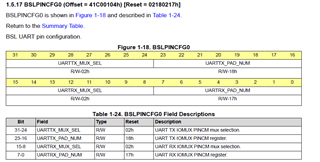
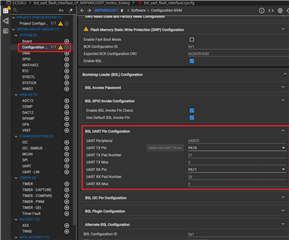
    Please check the BSLPINCFG0 register in our Technical Reference Manual. It is a field of NONMAIN, and BSL will scan the UART pin defined by this register. So you may need to change this field if you want to change UART pins. It could be configured in Sysconfig.


  • Hi Pengfei,

    the change of UARTs GPIOs are working. That is not my problem. The problem is the three other GPIOs I want to use.

    I`ve initalized them in the BSL_PI_UART_init():

    uint16_t BSL_PI_UART_init(uint8_t *buffer, uint16_t bufferSize) {
    
      DL_GPIO_reset(GPIOA);
      DL_GPIO_enablePower(GPIOA);
    
      BSL_initBuffers(buffer, bufferSize);
    
      /* Reset and enable power to peripheral */
      DL_UART_Main_reset(BSL_UART);
      DL_UART_Main_enablePower(BSL_UART);
    
      /* Initialize GPIOs */
      DL_GPIO_initPeripheralInputFunction(BSL_GPIO_UART_RX_PIN, BSL_GPIO_UART_RX);
      DL_GPIO_initPeripheralOutputFunction(BSL_GPIO_UART_TX_PIN, BSL_GPIO_UART_TX);
    
      DL_GPIO_initDigitalOutput(BSL_RE_IOMUX);
      DL_GPIO_clearPins(BSL_RE_PORT, BSL_RE_PIN);
    
      DL_GPIO_initDigitalOutput(LED_GREEN_IOMUX);
      // DL_GPIO_initDigitalOutput(LED_RED_IOMUX);
      // DL_GPIO_setPins(LED_PORT, LED_GREEN_PIN | LED_RED_PIN);
      DL_GPIO_setPins(LED_PORT, LED_GREEN_PIN);
      /* UART configuration */
      
      //skipped the rest of the code -> same as example
      
      /* Return the Plugin version info to the ROM BSL core */
      return FLASH_PLUGIN_VERSION_UART;
    }

    I´ve called GPIO_reset() and enablePower(). Then I initalized them as digital output and set one to low the other to high. Both not working. The one set to low has a pull up resistor and it will stay high

    So the problem is not the UART pins it is  PA3,11 and 15 as normal GPIOs.

    The corresponding header:

    #ifndef ti_msp_dl_config_h
    #define ti_msp_dl_config_h
    
    #include <ti/devices/msp/msp.h>
    #include <ti/driverlib/dl_common.h>
    #include <ti/driverlib/driverlib.h>
    #include <ti/driverlib/m0p/dl_core.h>
    
    /* GPIO configuration - UART */
    #define BSL_GPIO_UART_TX_PIN (IOMUX_PINCM1)
    #define BSL_GPIO_UART_RX_PIN (IOMUX_PINCM2)
    #define BSL_GPIO_UART_TX (IOMUX_PINCM1_PF_UART0_TX)
    #define BSL_GPIO_UART_RX (IOMUX_PINCM2_PF_UART0_RX)
    
    /* Definitions for UART */
    #define BSL_UART (UART0)
    #define BSL_UART_INTERRUPT_NUM (UART0_INT_IRQn)
    #define BSL_UART_CLOCK_SOURCE (DL_UART_MAIN_CLOCK_BUSCLK)
    #define BSL_UART_DEFAULT_BAUD ((uint32_t)9600U)
    #define BSL_UART_CLOCK ((uint32_t)32000000U)
    
    #define BSL_RE_PORT (GPIOA)
    #define BSL_RE_PIN (DL_GPIO_PIN_3)
    #define BSL_RE_IOMUX (IOMUX_PINCM8)
    
    /* Definitions for CRC */
    #define BSL_CRC (CRC)
    #define BSL_CRC_SEED ((uint32_t)0xFFFFFFFFU)
    
    #define LED_PORT (GPIOA)
    #define LED_GREEN_PIN (DL_GPIO_PIN_15)
    #define LED_GREEN_IOMUX (IOMUX_PINCM37)
    #define LED_RED_PIN (DL_GPIO_PIN_11)
    #define LED_RED_IOMUX (IOMUX_PINCM22)
    
    #endif /* ti_msp_dl_config_h */
    

  • And I tried a  "Project-less Debug" in order to attach to a running target in order to read out the registers but I always get  "Debug access within NONMAIN was disabled or enabled with password". 

  • It seems you did not add DL_GPIO_enableOutput() for GPIO output.

    Actually you could import a gpio goggle example from SDK and see what is the initial process of GPIO generated by SysConfig.

  • That was an easy fix. Sorry. I didn`t see that...