Part Number: MSPM0G1105
Other Parts Discussed in Thread: LP-MSPM0G3507
Tool/software:
Hi All,
1)
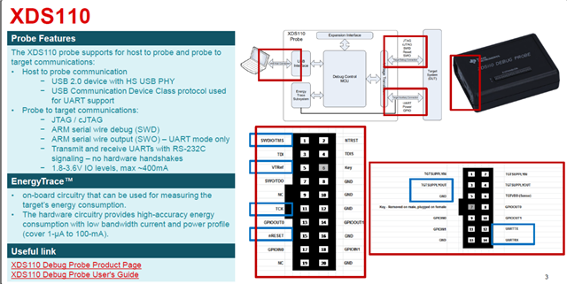
Is the connection between the XDS110 and the microcontroller correct?
Microcontroller XDS110 (CTI20)
SWDIO (34-pin) ⇔ SWDIO/TMS (1-pin)
SWCLK (35-pin) ⇔ SWCLK/TCK (11-pin)
VDD (6-pin) ⇒ VTREF (5-pin)?
NRST (4-pin) ⇔ nRESET (15-pin)?
VSS (7-pin) ⇒ GND (10, 12-pin)
2)
I do not want to use the probe's power supply function, but instead want to supply power to the board from a switching power supply or similar
to write to the microcontroller's Flash.
Should the microcontroller's VDD pin be connected to the XDS110's VTREF pin?
※Explanation
The purpose is to transmit the microcontroller's power supply voltage to the XDS110.
The XDS110's IO pin voltage is considered to be variable by a level shifter IC, etc.,
using the Voltage Translation function. Target
Is it acceptable to supply 3.3V from the board to the XDS110's VTREF pin?
I was unable to find the specifications for the VTREF pin.
3)
The NRST pin is also connected to an open-drain output reset IC on the board.
Is the XDS110's output open-drain?
4)
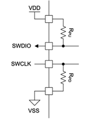
Regarding the processing of SWDIO (pin 34) and SWCLK (pin 35)
Only the connector is connected, and it remains open under normal conditions.
Are pull-up or pull-down resistors required on the board?
https://www.ti.com/lit/pdf/SLAU846 P.2254
Since the IC has internal pull-up and pull-down resistors, is it acceptable to leave the board open?
5)
The link to the Japanese version of the MSPM0G1105 datasheet is broken.
How can I obtain it?


Best Regards,
Ito