This thread has been locked.

If you have a related question, please click the "Ask a related question" button in the top right corner. The newly created question will be automatically linked to this question.

TMDSCNCD263P: AM263px Control Card + Automotive Ethernet add-on Board: PHY loopback failure

Part Number: TMDSCNCD263P
Other Parts Discussed in Thread: DP83TG720-EVM-AM2, SYSCONFIG

Tool/software:

Hi!

I am trying to enable Automotive Ethernet add-on Board (DP83TG720-EVM-AM2) on AM263px Control Card (TMDSCNCD263P PROC159A).

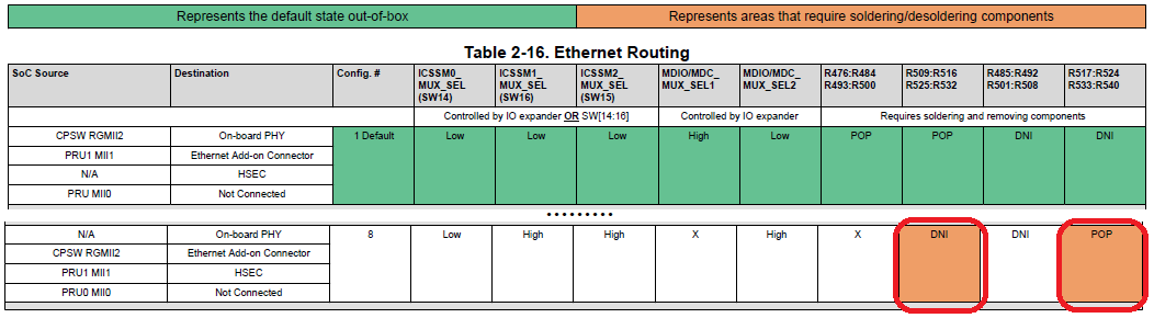
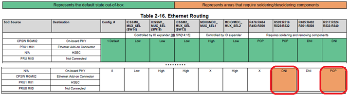
I re-soldered zero-ohm resistors on the control card according to Config. #8 in Table 2-16 from the control card User Guide.

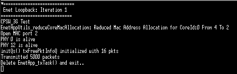
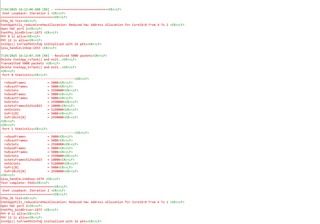
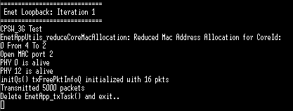
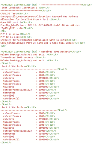
I am trying PHY loopback test from  Enet CPSW Loopback Example.

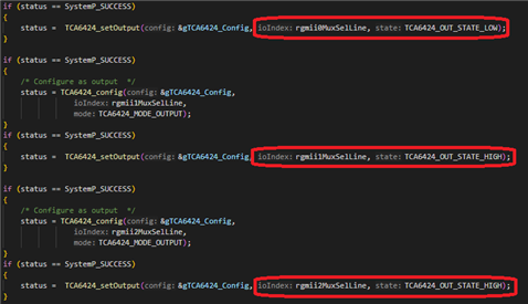
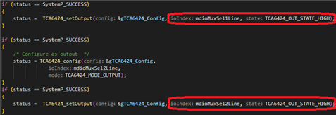
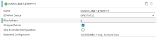
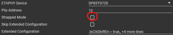
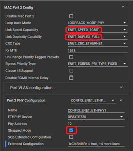
I made changes in the Sysconfig file from the example as described here.

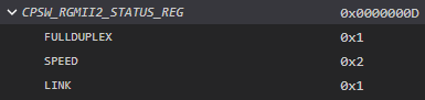
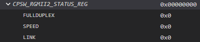
As a result, the transmission fails.

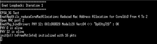
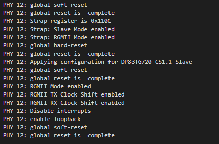
While checking the signals on the add-on PHY board, I observe 25 MHz on Tx clock pin.

As I understood from PHY documentation, this clock is provided by MAC, and it should be 125 MHz. Therefore, it looks like the problem is on MAC side.

I would be thankful for any suggestions for further debugging or proper configuration.

  • Hi,

    Can you also confirm the configuration of your SW14:16 on-board switches?

    Regards,
    Shaunak

  • Hi Shaunak,

    The code generated by Sysconfig correctly sets up the signals, which are controlled by SW14:16.

    I have checked the set voltage levels at corresponding pins, they are correct.

    In addition, I have tried to set SW14:16 manually, and it does not make any change.

    The code generated by Sysconfig connects CPSW MDIO bus to both on-board and add-on PHYs.

    As I understand, this should not be a problem, since the PHYs have different IDs.

    Are there any other things to check?

  • Hi,

    Just wanted to check if:
    SW14 - LOW
    SW15 - HIGH
    SW16 - HIGH

    Also, In the PinMux in Enet (CPSW), do you set it as RGMII?

    Also, in the top level board in Enet (CPSW), Do you select Automotive add-on-board?

    Regards,
    Shaunak

  • Just wanted to check if:
    SW14 - LOW
    SW15 - HIGH
    SW16 - HIGH

    Yes, set like above.

    Also, In the PinMux in Enet (CPSW), do you set it as RGMII?

    Yes.

    Also, in the top level board in Enet (CPSW), Do you select Automotive add-on-board?

    Yes.

  • Hello,

    Is there any update?

  • Hi Nikolay,

    Would it be possible to check the following:

    1. Rx clock (we see Tx clock incorrect, wanted to check Rx as well)

    This can also be some other issue with board, I do the same steps on my end and it works

    2. The Ethernet drivers/examples are the same as out-of-box config right? (Except the syscfg changes mentioned for PinMux)

    3. Is there any change made in the IO-Expander code?

    4. Can you share your binary which I can test on my local setup for AM263Px-CC + Auto PHY Board. This way we can isolate the issue to Hardware or Software

    Regards,
    Shaunak

  • Hi,

    1. Rx clock (we see Tx clock incorrect, wanted to check Rx as well)

    This can also be some other issue with board, I do the same steps on my end and it works

    Rx clock is 125 MHz, no problems here.

    2. The Ethernet drivers/examples are the same as out-of-box config right? (Except the syscfg changes mentioned for PinMux)

    Yes, only Sysconfig file was changed.

    The loopback example is from here:

    ti\mcu_plus_sdk_am263px_10_01_00_34\source\networking\enet\core\examples\enet_loopback\enet_cpsw_loopback\loopback_phy_end\am263px-cc\r5fss0-0_freertos

    3. Is there any change made in the IO-Expander code?

    No changes.

    4. Can you share your binary which I can test on my local setup for AM263Px-CC + Auto PHY Board. This way we can isolate the issue to Hardware or Software

    I tried to drag-and-drop the binary file, but it was not attached. I tried to use "Insert"-"Image/video/file" in the menu, but it also didn't work.

    So I am sharing the content of my syscfg. Since I only changed this file, the binary built with this content should be identical to mine.

    /**
     * These arguments were used when this file was generated. They will be automatically applied on subsequent loads
     * via the GUI or CLI. Run CLI with '--help' for additional information on how to override these arguments.
     * @cliArgs --device "AM263Px" --part "AM263P4" --package "ZCZ_S" --context "r5fss0-0" --product "MCU_PLUS_SDK_AM263Px@10.01.00"
     * @v2CliArgs --device "AM263P4-Q1" --package "NFBGA (ZCZ-S)" --context "r5fss0-0" --product "MCU_PLUS_SDK_AM263Px@10.01.00"
     * @versions {"tool":"1.21.2+3837"}
     */
    
    /**
     * Import the modules used in this configuration.
     */
    const eeprom             = scripting.addModule("/board/eeprom/eeprom", {}, false);
    const eeprom1            = eeprom.addInstance();
    const ethphy_cpsw_icssg  = scripting.addModule("/board/ethphy_cpsw_icssg/ethphy_cpsw_icssg", {}, false);
    const ethphy_cpsw_icssg1 = ethphy_cpsw_icssg.addInstance();
    const i2c                = scripting.addModule("/drivers/i2c/i2c", {}, false);
    const i2c1               = i2c.addInstance();
    const i2c2               = i2c.addInstance();
    const debug_log          = scripting.addModule("/kernel/dpl/debug_log");
    const dpl_cfg            = scripting.addModule("/kernel/dpl/dpl_cfg");
    const mpu_armv7          = scripting.addModule("/kernel/dpl/mpu_armv7", {}, false);
    const mpu_armv71         = mpu_armv7.addInstance();
    const mpu_armv72         = mpu_armv7.addInstance();
    const mpu_armv73         = mpu_armv7.addInstance();
    const mpu_armv74         = mpu_armv7.addInstance();
    const mpu_armv75         = mpu_armv7.addInstance();
    const general            = scripting.addModule("/memory_configurator/general", {}, false);
    const general1           = general.addInstance();
    const region             = scripting.addModule("/memory_configurator/region", {}, false);
    const region1            = region.addInstance();
    const section            = scripting.addModule("/memory_configurator/section", {}, false);
    const section1           = section.addInstance();
    const section2           = section.addInstance();
    const section3           = section.addInstance();
    const section4           = section.addInstance();
    const section5           = section.addInstance();
    const section6           = section.addInstance();
    const section7           = section.addInstance();
    const section8           = section.addInstance();
    const section9           = section.addInstance();
    const enet_cpsw          = scripting.addModule("/networking/enet_cpsw/enet_cpsw", {}, false);
    const enet_cpsw1         = enet_cpsw.addInstance();
    
    /**
     * Write custom configuration values to the imported modules.
     */
    eeprom1.$name = "CONFIG_EEPROM0";
    
    i2c1.$name           = "CONFIG_I2C0";
    i2c1.I2C.$assign     = "I2C2";
    i2c1.I2C.SCL.$assign = "UART0_RTSn";
    i2c1.I2C.SDA.$assign = "UART0_CTSn";
    i2c1.I2C_child.$name = "drivers_i2c_v1_i2c_v1_template2";
    
    i2c2.$name               = "CONFIG_I2C1";
    eeprom1.peripheralDriver = i2c2;
    i2c2.I2C.$assign         = "I2C0";
    i2c2.I2C.SCL.$assign     = "I2C0_SCL";
    i2c2.I2C.SDA.$assign     = "I2C0_SDA";
    i2c2.I2C_child.$name     = "drivers_i2c_v1_i2c_v1_template0";
    
    debug_log.enableUartLog            = true;
    debug_log.enableCssLog             = false;
    debug_log.uartLog.$name            = "CONFIG_UART0";
    debug_log.uartLog.UART.$assign     = "UART0";
    debug_log.uartLog.UART.RXD.$assign = "UART0_RXD";
    debug_log.uartLog.UART.TXD.$assign = "UART0_TXD";
    debug_log.uartLog.child.$name      = "drivers_uart_v2_uart_v2_template0";
    
    mpu_armv71.$name             = "CONFIG_MPU_REGION0";
    mpu_armv71.size              = 31;
    mpu_armv71.attributes        = "Device";
    mpu_armv71.accessPermissions = "Supervisor RD+WR, User RD";
    mpu_armv71.allowExecute      = false;
    
    mpu_armv72.$name             = "CONFIG_MPU_REGION1";
    mpu_armv72.size              = 15;
    mpu_armv72.accessPermissions = "Supervisor RD+WR, User RD";
    
    mpu_armv73.$name             = "CONFIG_MPU_REGION2";
    mpu_armv73.baseAddr          = 0x80000;
    mpu_armv73.size              = 15;
    mpu_armv73.accessPermissions = "Supervisor RD+WR, User RD";
    
    mpu_armv74.$name             = "CONFIG_MPU_REGION3";
    mpu_armv74.accessPermissions = "Supervisor RD+WR, User RD";
    mpu_armv74.baseAddr          = 0x70000000;
    mpu_armv74.size              = 21;
    
    mpu_armv75.$name      = "CONFIG_MPU_REGION4";
    mpu_armv75.baseAddr   = 0x70080000;
    mpu_armv75.size       = 14;
    mpu_armv75.attributes = "NonCached";
    
    general1.$name        = "CONFIG_GENERAL0";
    general1.stack_size   = 8192;
    general1.heap_size    = 1024;
    general1.linker.$name = "TIARMCLANG0";
    
    region1.$name                               = "MEMORY_REGION_CONFIGURATION0";
    region1.memory_region.create(7);
    region1.memory_region[0].type               = "TCMA";
    region1.memory_region[0].$name              = "R5F_VECS";
    region1.memory_region[0].auto               = false;
    region1.memory_region[0].size               = 0x40;
    region1.memory_region[1].type               = "TCMA";
    region1.memory_region[1].$name              = "R5F_TCMA";
    region1.memory_region[1].size               = 0x7FC0;
    region1.memory_region[2].type               = "TCMB";
    region1.memory_region[2].size               = 0x8000;
    region1.memory_region[2].$name              = "R5F_TCMB";
    region1.memory_region[3].$name              = "CPPI_DESC";
    region1.memory_region[3].auto               = false;
    region1.memory_region[3].manualStartAddress = 0x70080000;
    region1.memory_region[3].size               = 0x4000;
    region1.memory_region[4].$name              = "OCRAM";
    region1.memory_region[4].auto               = false;
    region1.memory_region[4].manualStartAddress = 0x70084000;
    region1.memory_region[4].size               = 0x17C000;
    region1.memory_region[5].type               = "FLASH";
    region1.memory_region[5].$name              = "FLASH";
    region1.memory_region[5].auto               = false;
    region1.memory_region[5].manualStartAddress = 0x60100000;
    region1.memory_region[5].size               = 0x80000;
    region1.memory_region[6].$name              = "SBL";
    region1.memory_region[6].size               = 0x40000;
    region1.memory_region[6].auto               = false;
    
    section1.load_memory                  = "R5F_VECS";
    section1.group                        = false;
    section1.$name                        = "Vector Table";
    section1.output_section.create(1);
    section1.output_section[0].$name      = ".vectors";
    section1.output_section[0].palignment = true;
    
    section2.load_memory                  = "OCRAM";
    section2.$name                        = "Text Segments";
    section2.output_section.create(5);
    section2.output_section[0].$name      = ".text.hwi";
    section2.output_section[0].palignment = true;
    section2.output_section[1].$name      = ".text.cache";
    section2.output_section[1].palignment = true;
    section2.output_section[2].$name      = ".text.mpu";
    section2.output_section[2].palignment = true;
    section2.output_section[3].$name      = ".text.boot";
    section2.output_section[3].palignment = true;
    section2.output_section[4].$name      = ".text:abort";
    section2.output_section[4].palignment = true;
    
    section3.load_memory                  = "OCRAM";
    section3.$name                        = "Code and Read-Only Data";
    section3.output_section.create(2);
    section3.output_section[0].$name      = ".text";
    section3.output_section[0].palignment = true;
    section3.output_section[1].$name      = ".rodata";
    section3.output_section[1].palignment = true;
    
    section4.load_memory                  = "OCRAM";
    section4.$name                        = "Data Segment";
    section4.output_section.create(1);
    section4.output_section[0].$name      = ".data";
    section4.output_section[0].palignment = true;
    
    section5.load_memory                             = "OCRAM";
    section5.$name                                   = "Memory Segments";
    section5.output_section.create(3);
    section5.output_section[0].$name                 = ".bss";
    section5.output_section[0].output_sections_start = "__BSS_START";
    section5.output_section[0].output_sections_end   = "__BSS_END";
    section5.output_section[0].palignment            = true;
    section5.output_section[1].$name                 = ".sysmem";
    section5.output_section[1].palignment            = true;
    section5.output_section[2].$name                 = ".stack";
    section5.output_section[2].palignment            = true;
    
    section6.load_memory                              = "OCRAM";
    section6.$name                                    = "Stack Segments";
    section6.output_section.create(5);
    section6.output_section[0].$name                  = ".irqstack";
    section6.output_section[0].output_sections_start  = "__IRQ_STACK_START";
    section6.output_section[0].output_sections_end    = "__IRQ_STACK_END";
    section6.output_section[0].input_section.create(1);
    section6.output_section[0].input_section[0].$name = ". = . + __IRQ_STACK_SIZE;";
    section6.output_section[1].$name                  = ".fiqstack";
    section6.output_section[1].output_sections_start  = "__FIQ_STACK_START";
    section6.output_section[1].output_sections_end    = "__FIQ_STACK_END";
    section6.output_section[1].input_section.create(1);
    section6.output_section[1].input_section[0].$name = ". = . + __FIQ_STACK_SIZE;";
    section6.output_section[2].$name                  = ".svcstack";
    section6.output_section[2].output_sections_start  = "__SVC_STACK_START";
    section6.output_section[2].output_sections_end    = "__SVC_STACK_END";
    section6.output_section[2].input_section.create(1);
    section6.output_section[2].input_section[0].$name = ". = . + __SVC_STACK_SIZE;";
    section6.output_section[3].$name                  = ".abortstack";
    section6.output_section[3].output_sections_start  = "__ABORT_STACK_START";
    section6.output_section[3].output_sections_end    = "__ABORT_STACK_END";
    section6.output_section[3].input_section.create(1);
    section6.output_section[3].input_section[0].$name = ". = . + __ABORT_STACK_SIZE;";
    section6.output_section[4].$name                  = ".undefinedstack";
    section6.output_section[4].output_sections_start  = "__UNDEFINED_STACK_START";
    section6.output_section[4].output_sections_end    = "__UNDEFINED_STACK_END";
    section6.output_section[4].input_section.create(1);
    section6.output_section[4].input_section[0].$name = ". = . + __UNDEFINED_STACK_SIZE;";
    
    section7.load_memory                  = "OCRAM";
    section7.$name                        = "Initialization and Exception Handling";
    section7.output_section.create(3);
    section7.output_section[0].$name      = ".ARM.exidx";
    section7.output_section[0].palignment = true;
    section7.output_section[1].$name      = ".init_array";
    section7.output_section[1].palignment = true;
    section7.output_section[2].$name      = ".fini_array";
    section7.output_section[2].palignment = true;
    
    section8.group                       = false;
    section8.load_memory                 = "CPPI_DESC";
    section8.type                        = "NOLOAD";
    section8.$name                       = "ENET_CPPI_DESC";
    section8.output_section.create(1);
    section8.output_section[0].$name     = ".bss:ENET_CPPI_DESC";
    section8.output_section[0].alignment = 128;
    
    section9.$name                       = "ENET_DMA_PKT_MEMPOOL";
    section9.load_memory                 = "OCRAM";
    section9.group                       = false;
    section9.type                        = "NOLOAD";
    section9.output_section.create(1);
    section9.output_section[0].$name     = ".bss:ENET_DMA_PKT_MEMPOOL";
    section9.output_section[0].alignment = 128;
    
    enet_cpsw1.$name                 = "CONFIG_ENET_CPSW0";
    enet_cpsw1.DisableMacPort1       = true;
    enet_cpsw1.cptsHostRxTsEn        = false;
    enet_cpsw1.macport2LoopbackMode  = "LOOPBACK_MODE_PHY";
    enet_cpsw1.macport2LinkDuplexity = "ENET_DUPLEX_FULL";
    enet_cpsw1.BoardType             = "am263px-cc-addon-auto";
    enet_cpsw1.macport2LinkSpeed     = "ENET_SPEED_1GBIT";
    enet_cpsw1.RGMII2.RD0.$used      = false;
    enet_cpsw1.RGMII2.RD1.$used      = false;
    enet_cpsw1.RGMII2.RD2.$used      = false;
    enet_cpsw1.RGMII2.RD3.$used      = false;
    enet_cpsw1.RGMII2.RX_CTL.$used   = false;
    enet_cpsw1.RGMII2.RXC.$used      = false;
    enet_cpsw1.RGMII2.TD0.$used      = false;
    enet_cpsw1.RGMII2.TD1.$used      = false;
    enet_cpsw1.RGMII2.TD2.$used      = false;
    enet_cpsw1.RGMII2.TD3.$used      = false;
    enet_cpsw1.RGMII2.TX_CTL.$used   = false;
    enet_cpsw1.RGMII2.TXC.$used      = false;
    enet_cpsw1.txDmaChannel[0].$name = "ENET_DMA_TX_CH0";
    enet_cpsw1.rxDmaChannel[0].$name = "ENET_DMA_RX_CH0";
    
    ethphy_cpsw_icssg1.enableCustomBoard = scripting.forceWrite(false);
    ethphy_cpsw_icssg1.$name             = "CONFIG_ENET_ETHPHY1";
    enet_cpsw1.ethphy2                   = ethphy_cpsw_icssg1;
    ethphy_cpsw_icssg1.isStrappedPhy     = true;
    
    /**
     * Pinmux solution for unlocked pins/peripherals. This ensures that minor changes to the automatic solver in a future
     * version of the tool will not impact the pinmux you originally saw.  These lines can be completely deleted in order to
     * re-solve from scratch.
     */
    enet_cpsw1.MDIO.$suggestSolution          = "MDIO";
    enet_cpsw1.MDIO.MDC.$suggestSolution      = "MDIO_MDC";
    enet_cpsw1.MDIO.MDIO.$suggestSolution     = "MDIO_MDIO";
    enet_cpsw1.RGMII1.$suggestSolution        = "RGMII2";
    enet_cpsw1.RGMII1.RD0.$suggestSolution    = "PR0_PRU0_GPIO0";
    enet_cpsw1.RGMII1.RD1.$suggestSolution    = "PR0_PRU0_GPIO1";
    enet_cpsw1.RGMII1.RD2.$suggestSolution    = "PR0_PRU0_GPIO2";
    enet_cpsw1.RGMII1.RD3.$suggestSolution    = "PR0_PRU0_GPIO3";
    enet_cpsw1.RGMII1.RX_CTL.$suggestSolution = "PR0_PRU0_GPIO4";
    enet_cpsw1.RGMII1.RXC.$suggestSolution    = "PR0_PRU0_GPIO6";
    enet_cpsw1.RGMII1.TD0.$suggestSolution    = "PR0_PRU0_GPIO11";
    enet_cpsw1.RGMII1.TD1.$suggestSolution    = "PR0_PRU0_GPIO12";
    enet_cpsw1.RGMII1.TD2.$suggestSolution    = "PR0_PRU0_GPIO13";
    enet_cpsw1.RGMII1.TD3.$suggestSolution    = "PR0_PRU0_GPIO14";
    enet_cpsw1.RGMII1.TX_CTL.$suggestSolution = "PR0_PRU0_GPIO15";
    enet_cpsw1.RGMII1.TXC.$suggestSolution    = "PR0_PRU0_GPIO16";
    enet_cpsw1.RGMII2.$suggestSolution        = "RGMII1";
    

  • Hi Nikolay,

    I tried running the same and it worked. The only changes I did were w.r.t to the PHY address (apart from the documentation)

    When you run your application, you will see the PHY Alive come up with the address. In my case I saw PHY0 and PHY8, but my Syscfg EthPhy address was configured as 12. You can check the same once as I see in your syscfg as well the PHY address is 12. In your application log, if you see "PHY8", Change this address to 8 from 12 and re-build and try again. Let's see if this solves the issue

    Regards,
    Shaunak

  • Hi Shaunak,

    I tried what you suggested, but it didn't solve the issue.

    Apparently, the problem is with HW, since everything is working for you.

    I am waiting for a new set of HW and will update after trying new EVK boards.

  • Hello Shaunak,

    I have tried a new set of AM263Px-CC + Auto PHY. However, exactly the same issue remains. I need to debug further.

    1) If you know how to share a binary here, could you please share yours?

    2) Is your HW configuration same as config. #8 in the table? No other changes in HW?

  • Hi Nikolay,

    Shaunak is OOO this week. Please expect a reply the coming week.

    Regards,

    Aswin

  • Hi Nikolay,

    Apologies for a delayed response, I was Out of Office in the last week.

    One thing I wanted to check here was, is the link partner for the Auto-PHY configured in a particular master or slave mode? You can follow this FAQ: 

     [FAQ] LP-AM261: Unable to get MAC Port link up with AM261x-LP + Automotive PHY add-on-board (DP83TG720/721) 

    (FAQ is for AM261x, but same steps can be followed for AM263Px as well). I wanted to check if this helps because on my end, I connect the AM263Px-CC + Auto PHY with a RGMII Converter board which is master (so my PHY is in slave mode). If the link partner and PHY both are trying to be master or both slave, there will be issues on the MDI bus leading to no MAC Port link up as seen in the app logs posted in original question.

    Regards,
    Shaunak

  • Hi Shaunak,

    Thanks for suggestion, unfortunately it didn't help.

    1) I tried all the options for .MasterSlaveMode field as you suggested, neither of them worked.

    2) I was able to link up MAC and Auto-PHY after unchecking "Strapped Mode" in SysConfig.

    In this case, MAC transmits data, but it is not received after loopback.

    While checking the signals, I still see 2.5 MHz Tx clock and 125 MHz Rx clock.

    3) I checked RGMII2_STATUS register values afer link-up event.

    Working case (on-board PHY):

    Non-working case (addon Auto-PHY):

    Looks like configuration has not been applied to MAC in case of Auto-PHY.

    4) I enabled debug log in the PHY part of the driver.

    It does not show anything wrong. Looks like there are no problems with MDIO communication and PHY itself.

    Is there anything else to check, without digging into the driver?

  • Hi Shaunak,

    1) Since you have a working configuration, would it be possible to get all the details of your configuration: sysconfig settings, additional driver configuration (if any), strap resistors on PHY? Maybe I can try to reproduce it.

    2) I am comparing working case (on-board PHY) and non-working case (addon auto-PHY). I see a difference in PN_MAC_STATUS_REG register after link-up event:

    Working case (on-board PHY): EXT_GIG and EXT_FULLDUPLEX fields are set to 1

    Non-working case (addon auto-PHY): EXT_GIG and EXT_FULLDUPLEX fields are set to 0

    Does this ring a bell to you?

  • Hi Nikolay,

    I am currently investigating the issue and appreciate your patience.

    Allow me some time. I will share a working project configuration with you.

    Regards,

    Aswin

  • phy_loopback.ziphttps://e2e.ti.com/cfs-file/__key/communityserver-discussions-components-files/908/enet_5F00_cpsw_5F00_loopback_5F00_phy_5F00_end_5F00_am263px_2D00_cc_5F00_r5fss0_2D00_0_5F00_freertos_5F00_ti_2D00_arm_2D00_clang.out

    Hi Nikolay,

    I have attached my project. I have tested it on my side on CC board and it is working. It is in zip format. Import it in CCS and build the project.

    I have also attached my .out file. 
    I am able to see the outputs. Please see the screen snip below

    Can you check the following in your setup,

    1. Can you reconfirm if SW14, SW15 and SW16 switches on the control card are LOW, LOW and LOW respectively.

    2. Have you made any changes in PHY add on board or on the EVM?

    3. The sysconfig file will be available in the project. Can you check it with yours as well.

    Regards,

    Aswin

  • Hi Aswin,

    Thanks a lot for investigating this issue. I flashed your binary, but it did not work on my side.

    Therefore, it is clear now, that my issue is related to HW, since the same SW is working for you.

    What is your HW configuration? Did you make any changes on the CC board or PHY add-on board?

    Answering your questions:

    1. I set the switches as you wrote, but it did not help.

    2. No changes on the PHY add-on board.

    On the CC board I re-soldered zero-ohm resistors according to config. #8 from the table in EVM user guide.

    3. I could not check the Sysconfig file directly (the sources in your project are linked from SDK folder).

    However,  .c and .h files generated by Sysconfig in your project are identical to mine.

  • Hi Nikolay,

    This would be a hardware configuration issue.

    To double check, can you share your project and out files so that I can check it on my side.

    Regards,

    Aswin

  • Hi Aswin,

    I am sharing my project. The built files are included.

    enet_cpsw_loopback_phy_end_am263px-cc_r5fss0-0_freertos_ti-arm-clang.zip

    Since it is a HW issue, may I know your HW configuration?

    Did you do any re-soldering of zero-ohm jumpers on the CC board?

    Thank you,

    Nikolay

  • Hi Nikolay, 

    The project that you have sent me is working on my side. Here is the output of the debug build.

    The SW pins should be like

    - SW14 : LOW

    - SW16 : HIGH

    - SW15 : HIGH (The switch orientation inverted compared to SW14 and SW15)

    I apologize for my mistake in the earlier message when I said all should be low.

    Regarding the resistor configurations,

    On my setup only the following resistors were populated( with zero ohm resistors)

    R517: R524 and R333: R540

    Regards,

    Aswin

  • Hi Nikolay,

    May I know if DNI is done on R509:R516.

    Sorry for reconfirming again. The reason I wanted to know is because that when I checked with the networking team I came to know that according to Control Card documentation recommendation (after doing DNI and POP on the specified set of resistors), we will not get both PHY alive 0 and PHY alive 12.

    PHY Alive for Auto PHY only is expected. But on the debug logs above I can see that there are two PHY Alive logs.

    Regards,

    Aswin

  • Hi Aswin,

    Yes, R509:R516 DNI is done. My configuration is as follows:

    DNI - R509:R516, R525:R532;

    POP - R517:R524, R533:R540.

    In your configuration, you got both PHY 0 and PHY 12 alive logs. So it may not be an problem, since your configuration is working.

    I will try your configuration (only populate R517: R524 and R533: R540), and update.

  • Hi Nikolay,

    Can you let us know what exactly was different in the configuration, which you changed and it worked? Was it the doing only the "POP" resistors and not the "DNI" resistors (As originally pointed in the documentation). Reason for asking this is so that we can update the documentation based on the learning from here.

    Regards,
    Shaunak

  • Hi Aswin,

    I have tried your configuration (default CC board + populated R517: R524 and R533: R540), and auto-PHY is now working well on my side too.

    After checking the schematic, it looks very weird to me, that soldering back  R509:R516 and R525:R532 made a difference.

    Nevertheless, now I have a working configuration to start with.

    So the problem from the original post is solved.

    Thanks for support.

  • Hi Shaunak,

    My initial non-working configuration was #8 from Table 2-16 from CC board user guide:

    DNI - R509:R516, R525:R532;

    POP - R517:R524, R533:R540.

    I changed it to the configuration, which Aswin shared: soldered back R509:R516, R525:R532. After this change auto-PHY is working well.

    I do not know yet, why it helped. According to the schematic, it should not make any difference.

  • Hi Nikolay,

    Thanks for the information