This thread has been locked.

If you have a related question, please click the "Ask a related question" button in the top right corner. The newly created question will be automatically linked to this question.

AM2432: Sigma-Delta (SDFM) Fast Detect

Part Number: AM2432
Other Parts Discussed in Thread: SYSCONFIG

Tool/software:

Hi experts,

I am working on the Sigma-Delta (SDFM) examples with Motor Control SDK 09.02.00.11 looking at the Fast Detect and having some questions:

1) The PRU ICSS PWM TZ_OUT signal (for Fast Detect) is an active-high signal. What do I need to change at the SDFM firmware to invert the polarity of the PRU ICSS PWM TZ_OUT signal?

2) It seems that the Fast Detect only works if the Fast Detect option is enabled for CH0. If I disable the Fast Detect for CH0, it no longer works for the other channels. Why is that, and what do I need to change to make it work?

3) When will the new Motor Control SDK be released?

Thanks!

Best regards,

Jan

  • 1) The PRU ICSS PWM TZ_OUT signal (for Fast Detect) is an active-high signal. What do I need to change at the SDFM firmware to invert the polarity of the PRU ICSS PWM TZ_OUT signal?

    The polarity of the PRU ICSS PWM TZ output for fast detect cannot be inverted through software, as it is completely hardware-driven. Therefore, you would need to use external hardware to invert the output.

    It seems that the Fast Detect only works if the Fast Detect option is enabled for CH0. If I disable the Fast Detect for CH0, it no longer works for the other channels. Why is that, and what do I need to change to make it work?

    I will check on this and get back to you.

    When will the new Motor Control SDK be released?

    It is planned for this month!

    Thanks & Regards,

    Achala Ram

  • Thank you for your fast reply!

    The polarity of the PRU ICSS PWM TZ output for fast detect cannot be inverted through software, as it is completely hardware-driven. Therefore, you would need to use external hardware to invert the output.

    OK, that means for the Fast Detect the complete path (SDFM-firmware -> PRU PWM TZ module -> chip output) is hardware-driven?

    Does that also apply to the free-running over-current comparators? Can the polarity of the TZ_OUT signal be inverted by using the over-current comparators and adapting the SDFM firmware to change the polarity of the signals driving the PRU PWM TZ module?

    I will check on this and get back to you.

    Do you already have an answer for this?

    It is planned for this month!

    Thanks!

    I am also having issues getting the free-running over-current comparators into operation. As soon as I enable them in the .syscfg, the SDFM output samples show strange behaviour. What are the common pitfalls, and what steps are required to properly activate the over-current comparators? Are there any specifig settings that need special attention?

  • Do you already have an answer for this?

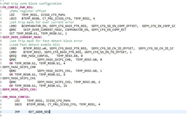
    Yes, there is a bug: the PWM trip register is configured only when Channel 0 is enabled! Please update FN_CONFIG_PWM_REG with the code below to remove the dependency on Channel 0

    OK, that means for the Fast Detect the complete path (SDFM-firmware -> PRU PWM TZ module -> chip output) is hardware-driven?

    Yes, the SDFM firmware doesn't perform any comparisons; it simply enables fast detect. All comparisons are handled by the fast detect block.

    Please refer to the following links for more details on fast detect and the trip zone:

    https://software-dl.ti.com/processor-industrial-sw/esd/motor_control_sdk/am243x/09_02_00_11/docs/api_guide_am243x/SDFM_DESIGN.html#autotoc_md309

    Sections: 6.4.5.2.2.3.5.3 Sigma Delta Description, 6.4.10 PRU_ICSSG PWM Module AM64x/AM243x Technical Reference Manual (Rev. H)

    Does that also apply to the free-running over-current comparators? Can the polarity of the TZ_OUT signal be inverted by using the over-current comparators and adapting the SDFM firmware to change the polarity of the signals driving the PRU PWM TZ module?

    Regarding overcurrent, the firmware first performs a threshold comparison and then writes to the PWM register to generate the trip signal on the PRU PWM TZ block. The PWM TZ has a software overcurrent error option, so the firmware writes a '1' when the sample value crosses the threshold limits. There is no option to change the polarity, and the current firmware does not support it. But, you can look this logic: write the software overcurrent error bit when the values are within the limits and reset the PWM when the values cross the limits. This way you can get reversed output on the TZ pin.


    PWM trip register 6.4.14.5.70 ICSSG_PWM0 Register (Offset = 130h) [reset = X]

    am also having issues getting the free-running over-current comparators into operation. As soon as I enable them in the .syscfg, the SDFM output samples show strange behaviour. What are the common pitfalls, and what steps are required to properly activate the over-current comparators? Are there any specifig settings that need special attention?

    No additional steps are required; simply enabling it through SysConfig should be sufficient. Could you please share which example and SDK version you are using? Also, please provide details on any additional configurations you've made in SysConfig beyond what's provided in the default SDK example

    Thanks & regards,

    Achala Ram

  • No additional steps are required; simply enabling it through SysConfig should be sufficient. Could you please share which example and SDK version you are using? Also, please provide details on any additional configurations you've made in SysConfig beyond what's provided in the default SDK example

    Thanks! It seems the comparators are working as expected by simply enabling them in the SysConfig.

    However, occasionally - after resetting and reloading the example multiple times - the output samples show unexpected behavior: output values exceed the expected maximum values defined by the SINC filter type and OSR.

    What is the reason for this?

    Used example: icss_sdfm_three_channel_single_pru_mode
    SDK: Motor Control SDK 09.02.00.11

    I used the default settings, enabled the comparators, configured ePWM for clocking, set the clock to 12.5 MHz and set the clock source individually for each channel.

    Thanks!

  • Hi Jan,

    Could you please test the clock generation option, such as eCAP, and observe the behavior?

    When using an external clock, that has jitter or variations, or if the clock isn't exactly what you're configuring in SysConfig, the firmware will sample incorrectly. This is because the current firmware achieves sample timing through IEP CMP event. Jitter or variations in the external clock source (especially when each channel has an individual clock source) can cause issues. 

    We have an alternative firmware designed for these types of use cases, which will be available in the next release planned for this month

    Thanks & Regards,

    Achala Ram

  • Thanks for that input. I tried out the PRU IEP CLK generation and unfortunately still observe wrong sampling. However, when I disable the over-current comparators, the sampling works correctly (no other settings were changed).

    I also notice wrong sampling when slightly changing the TBPRD register of the ePWM used for SDSYNC while the system is running. The trigger point is configured so that the NC sampling should be done before a sync0 event occurs.

    Is there an explanation for this behavior? Why does a small change in the TBPRD register lead to undefined or incorrect sampling - and only when the over-current comparators are eneabled?

    Thanks!

  • Is there an explanation for this behavior? Why does a small change in the TBPRD register lead to undefined or incorrect sampling - and only when the over-current comparators are eneabled?

    I will look into this and get back to you. In the meantime, could you please share the SysConfig settings for the SDFM parameters? Also, what EPWM frequency are you setting, and what changes are you making to the TBPRD register?

    Thanks & Regards,

    Achala Ram

  • Is there already an update for this?

    Used example: icss_sdfm_three_channel_single_pru_mode
    SDK: Motor Control SDK 09.02.00.11

    I'm using the default settings of the example (NC OSR 64; First Trigger Point (µs) 15; OC OSR 16), enabled the comparators, set the SDFM clock to 12.5 MHz, and set the clock source individually for each channel.


    EPWM frequency is 8 kHz (default from example). Regarding the TBPRD register: I'm slightly changing the TBPRD register while the system is running.

    Thanks & Regards

  • I'm using the default settings of the example (NC OSR 64; First Trigger Point (µs) 15; OC OSR 16), enabled the comparators, set the SDFM clock to 12.5 MHz, and set the clock source individually for each channel.

    Hi Jan, 

    are you setting the clock divider correctly for 12.5MHz for ECAP in sdfm_example.c as described in the documentation: https://software-dl.ti.com/processor-industrial-sw/esd/motor_control_sdk/am243x/09_02_00_11/docs/api_guide_am243x/EXAMPLES_MOTORCONTROL_SDFM.html#autotoc_md97. 

    We did not observe any high values with internal clock options at 12.5MHz, with the same configuration as yours.

    Is there an explanation for this behavior? Why does a small change in the TBPRD register lead to undefined or incorrect sampling - and only when the over-current comparators are eneabled?

    This issue will cause problems in continuous mode, but for trigger mode if all three continuous samples are being taken within one EPWM cycle it should not cause a problem. If the changes to the TB register are significant, it could lead to issues. Could you please share the changes you made to the TB register, including the specific value you changed, so that I can reproduce this on my setup and take a closer look?

    Thanks & Regards,

    Achala Ram