This thread has been locked.

If you have a related question, please click the "Ask a related question" button in the top right corner. The newly created question will be automatically linked to this question.

AM2432: The GPIO external 10K resistor is pulled up, but the GPIO pin level is not monotonic during the power on process

Part Number: AM2432

Tool/software:

Hi:

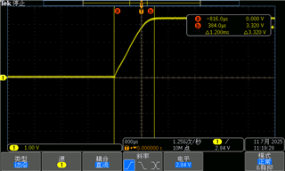
  We found in our testing that multiple GPIO external 10K resistors of AM2432 were pulled up to VCCIO, which was 3.3V. However, during the power on process, the GPIO pin level was not monotonic. We synchronously tested the GPIO level and the VCCIO level when powered on together, as shown in Figures 1 and 2. The VCCIO level was monotonic, so this problem is not caused by the power supply. I have consulted a lot of information, and my conclusion is that many GPIO of AM2432 are in a floating state during the reset period and after reset release (but before software initialization), which makes the parasitic capacitance of the pins easy to cause interference during power on. Is my understanding correct? We hope TI can provide me with a more authoritative and credible explanation regarding this issue. Thank you!

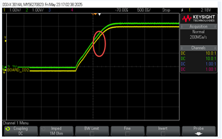
Figure 1 and 2 GPIO Y7 test power up

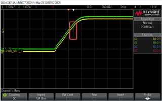
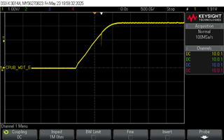
Figure 3 and 4 GPIO V7 test power up

  • Hi Zhanglong,

    Once the power has ramped, Y7 and V7 pins are inputs with pullDowns enabled by default (reset values). Please refer to table Pad Configuration Ball Names in the device TRM for the default settings of every multiplex-able pin.

    I think that during power ramp, the pin state should be considered as undefined. I'm not sure about the exact cause of the glitch you observed. It may be due to internal switching of the states of the IO buffers/pull resistors.

    Regards,

    Stan

  • Hi :


    sorry,I don't understand what you mean, according to the power-up timing of AM2432, VCCIO is powered up first, and our design is to pull-up GPIO Y7 and V7, so the levels of GPIO_V7 and Y7 are synchronized with VCCIO, and the power-up is not yet completed at this time, so we haven't configured GPIOs . In addition, according to the AM2432's datasheet, the state of the GPIOs at the reset device pins is uncertain, so I think this is due to the pin characteristics, and has nothing to do with my design!

    and can you test in your lab? whether the EVM has this prolem.

  • Zhanglong,

    Please disregard my statement about pulldowns. Also, I never mentioned your design by assuming those pins are connected to nothing else than 10k pullups. Can you please confirm this? That is, is there another circuitry connected to the two pins?

    AM2432's datasheet, the state of the GPIOs at the reset device pins is uncertain,

    Correct, during reset these IOs are disconnected from input and output buffers and from pulls as well.

  • Hi Stanislav Stilanov:

         I can confirm my design,these pins are connected to nothing else than 10k pullups.I also suggest you test your EVM ,thank you.

  • HI:

     Any progress on this issue?thank you

  • Hi Zhanglong,

    I do not observe on EVM the glitch you are observing. However, I think I need to try with a better oscilloscope to double check.

  • Hi Zhanglong,

    Can you please capture the above ramp plot with the MCU_PORz included.

    The reset is expected to be low during the supply ramp.

    Do you have any of the IO supply group VDDSHVx connected to 1.8V and have any GPIOs pulled to 1.8V.

    Can you please capture a plot for one of the IO connected to 1.8V.

    Regards,

    Sreenivasa

  • Hi Kallikuppa Sreenivasa:

         I capture the above ramp plot with the MCU_PORz included.As shown in the figure below,The reset is  low during the supply ramp.


         we  VDDSHVx connected to 3.3V.no 1.8V

  • Hi Zhanglong,

    Thank you.

    We are reviewing the inputs internally.

    I will update once i hear from the experts.

    Regards,

    Sreenivasa

  • Hi Zhanglong,

    Couple of quick questions.

    Can you measure the 3.3V supply slew rate.

    Can you share the CAP_VDDSx implementation details - cap value used, cap package size and the voltage rating.

    Regards,

    Sreenivasa

  • Hi Kallikuppa Sreenivasa:

       Thank for your reply.

        1、3.3V supply slew rate,As shown in the figure below.


       2、The CAP_VDDSx implementation details of my design


  • Hi Zhanglong,

    Thank you for the inputs.

    Although this may not be related to the issue discussing, we are recommending a 3.3uF cap for C290.

    Please update the cap value to 3.3uF.

    Regards,

    Sreenivasa


  • I'm not sure why Sreenivasa told you C290 needed to be 3.3uF. I assume C290 is connected to pin L13 (CAP_VDDSHV5) based on the signal name. If so, it should be 6.3V or greater, 0.8uF to 1.5μF. I think Sreenivasa was thinking about the capacitor requirement for pin K15 (CAP_VDDSHV_MMC1), which should have a 6.3V or greater, 3.3μF ±20% capacitor connected to it if you are using the internal SDIO_LDO.

    The IO cells implemented on pins Y7 and V7 were designed to operate at 1.8v or 3.3v mode. There is an internal supply detector mechanism that configures the IO in the appropriate mode based on the IO supply voltage level. During the mode transition from 1.8v mode to 3.3v mode or vice versa, it is possible for the IO to produce glitches on the signal. This doesn't cause any issue for the AM243x device.

    Regards,
    Paul

  • Hello Paul, 

    Thank you for the inputs. 

    I may have assumed the pin to be CAP_VDDSHV_MMC1 since i saw a 4.7uF cap. 

    The CAP_VDDSHV_MMC1 pin must always be connected via a 3.3-μF ±20% capacitor to VSS

    Regards,

    Sreenivasa

  • Hi Paul:

      Thank you for the reply.

      1、my device al  IO supply voltage is 3.3 ,no 1.8v mode transition to 3.3v mode.

      2、my device no use SDIO interface ,so according am2432 datasheet the CAP_VDDSHV_MMC1 must be connected directly to VSS.

  • Hi Kaillikuppa Sreenivasa.

      Thank you for the reply.

      1、my device al  IO supply voltage is 3.3 ,no 1.8v mode transition to 3.3v mode.

      2、my device no use SDIO interface ,so according am2432 datasheet the CAP_VDDSHV_MMC1 must be connected directly to VSS.

    3.Now we design CAP_VDDS5  connected  a 4.7 uF  4.7uF cap,Is there a connection to the Y7 and V7 problem?

  • In my previous reply, I specifically stated "if you are using the internal SDIO_LDO." when I mentioned the capacitor requirement for pin K15 (CAP_VDDSHV_MMC1).

    I agree both pin H17 (VDDA_3P3_SDIO) and pin K15 (CAP_VDDSHV_MMC1) should be connected to VSS if you are not using the internal SDIO_LDO to power pins L14 and L15 (VDDSHV5). In this case, you do not need to connect a capacitor to pin K15.

    I realize you are not purposefully operating the IO power rail for pins Y7 and V7 (VDDSHV2) at 1.8V, but the IO cell assumes it is operating at 1.8V initially as the IO power rail is ramping up. It automatically changes to 3.3V mode as the potential applied to the IO power rail continues to ramp above 1.8V on its way to 3.3V. The glitch you see happens when the IO cell changes its mode of operation. There is not anything you can do to change how the IO cell operates.

    You should not connect a 4.7uF to pin L13 (CAP_VDDSHV5). This may cause the device to have unexpected operation. The capacitor connected to this pin must be a 6.3V or greater, 0.8uF to 1.5μF capacitor. The capacitor selected must provide a capacitance within the defined range after it has been derated for DC-bias, operating temperature, and aging effects.

    Regards,
    Paul

  • Hi Guru:

       Thank you for reply.

    I realize you are not purposefully operating the IO power rail for pins Y7 and V7 (VDDSHV2) at 1.8V, but the IO cell assumes it is operating at 1.8V initially as the IO power rail is ramping up. It automatically changes to 3.3V mode as the potential applied to the IO power rail continues to ramp above 1.8V on its way to 3.3V. The glitch you see happens when the IO cell changes its mode of operation. There is not anything you can do to change how the IO cell operates

     I didn't understand your explanation, you mean the initial voltage of the IO supply is 1.8V, but since my design is 3.3V,  It automatically changes to 3.3V mode as the potential applied to the IO power rail continues to ramp above 1.8V on its way to 3.3V?

    You should not connect a 4.7uF to pin L13 (CAP_VDDSHV5). This may cause the device to have unexpected operation. The capacitor connected to this pin must be a 6.3V or greater, 0.8uF to 1.5μF capacitor. The capacitor selected must provide a capacitance within the defined range after it has been derated for DC-bias, operating temperature, and aging effects

     I connect a 1uF to pin L13 (CAP_VDDSHV5),After retesting, it was found that the above problem still existed, so it was not a problem caused by improper C290 selection.

  • You are correct. The IO cell monitors its own power rail and automatically changes from 1.8V mode to 3.3V mode as its IO power supply voltage continues to increase above 1.8V on its way to 3.3V. The opposite will happen as the IO power rail voltage decays. The IO cell will automatically change back to 1.8V mode as the IO supply voltage drops below 3.3V and approaches 1.8V.

    The capacitor connected to pin L13 (CAP_VDDSHV5) doesn't have any effect on the IO cells associated with pins Y7 and V7, which are powered from pins R10, R8, and T9 (VDDSHV2). The glitch you see is not related to the value of any capacitor. It is a function of how the IO cell works. As mentioned in my previous post, there is nothing you can do to change how the IO cell works. However, connecting the wrong value capacitor can cause other problems.

    Typically, a glitch on one of the AM243x pins is not an issue because the entire system is held in reset until all power supplies and clock sources are valid. You may need to insert a signal switch that blocks the glitch from propagating during power up if it is causing problems for your system.

    Regards,
    Paul

  • Hi Guru:

        Thank you for reply,this question has been bothering me for a long time. thank you, again.

  • Have checked with customer, close this thread.

    Thanks for help Paul and Sreenivasa.

    Zekun

  • Hello Zekun,

    Thank you.

    Regards,

    Sreenivasa