AM2612: Why do PWMA and PWMB generated by PWM always have random overlapping high parts at the end of timing?

Part Number: AM2612

Tool/software:

Dear TI experts,

We now use AM2612 r5f 4 channel PWM module to cooperate with high-speed relay output.

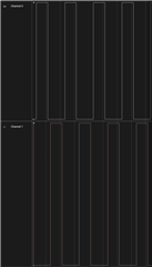
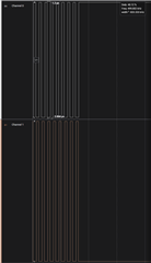
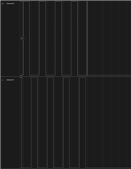
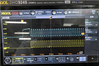
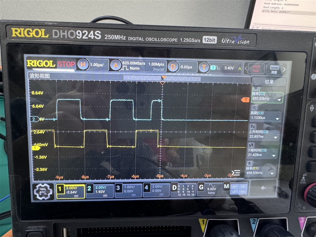
We hope generate PWMA&B pulse for a specified period on GPIO output is closed or opened and the waveforms of PWMA and PWMB are exactly inverted.

Now the waveform has a problem like the following picture: the yellow is PWMA, the blue is PWMB. There are random overlapping high parts when the timer clock is timeout, which can't be permitted.

But I don't know how to prevent it.

Please find the attachment for the example.syscfg file.

/**
 * These arguments were used when this file was generated. They will be automatically applied on subsequent loads
 * via the GUI or CLI. Run CLI with '--help' for additional information on how to override these arguments.
 * @cliArgs --device "AM261x_ZFG" --part "AM2612" --package "ZFG" --context "r5fss0-0" --product "MCU_PLUS_SDK_AM261x@10.00.01"
 * @v2CliArgs --device "AM2612" --package "NFBGA (ZFG)" --context "r5fss0-0" --product "MCU_PLUS_SDK_AM261x@10.00.01"
 * @versions {"tool":"1.23.0+4000"}
 */

/**
 * Import the modules used in this configuration.
 */
const eeprom             = scripting.addModule("/board/eeprom/eeprom", {}, false);
const eeprom1            = eeprom.addInstance();
const ethphy_cpsw_icssg  = scripting.addModule("/board/ethphy_cpsw_icssg/ethphy_cpsw_icssg", {}, false);
const ethphy_cpsw_icssg1 = ethphy_cpsw_icssg.addInstance();
const pmic               = scripting.addModule("/board/pmic/pmic", {}, false);
const pmic1              = pmic.addInstance();
const edma               = scripting.addModule("/drivers/edma/edma", {}, false);
const edma1              = edma.addInstance();
const epwm               = scripting.addModule("/drivers/epwm/epwm", {}, false);
const epwm1              = epwm.addInstance();
const epwm2              = epwm.addInstance();
const epwm3              = epwm.addInstance();
const epwm4              = epwm.addInstance();
const gpio               = scripting.addModule("/drivers/gpio/gpio", {}, false);
const gpio1              = gpio.addInstance();
const gpio2              = gpio.addInstance();
const gpio3              = gpio.addInstance();
const gpio4              = gpio.addInstance();
const gpio5              = gpio.addInstance();
const gpio6              = gpio.addInstance();
const gpio7              = gpio.addInstance();
const gpio8              = gpio.addInstance();
const gpio9              = gpio.addInstance();
const gpio10             = gpio.addInstance();
const gpio11             = gpio.addInstance();
const gpio12             = gpio.addInstance();
const gpio13             = gpio.addInstance();
const gpio14             = gpio.addInstance();
const gpio15             = gpio.addInstance();
const gpio16             = gpio.addInstance();
const gpio17             = gpio.addInstance();
const gpio18             = gpio.addInstance();
const i2c                = scripting.addModule("/drivers/i2c/i2c", {}, false);
const i2c1               = i2c.addInstance();
const i2c2               = i2c.addInstance();
const i2c3               = i2c.addInstance();
const pruicss            = scripting.addModule("/drivers/pruicss/pruicss", {}, false);
const pruicss1           = pruicss.addInstance();
const pruicss2           = pruicss.addInstance();
const clock              = scripting.addModule("/kernel/dpl/clock");
const debug_log          = scripting.addModule("/kernel/dpl/debug_log");
const dpl_cfg            = scripting.addModule("/kernel/dpl/dpl_cfg");
const mpu_armv7          = scripting.addModule("/kernel/dpl/mpu_armv7", {}, false);
const mpu_armv71         = mpu_armv7.addInstance();
const mpu_armv72         = mpu_armv7.addInstance();
const mpu_armv73         = mpu_armv7.addInstance();
const mpu_armv74         = mpu_armv7.addInstance();
const mpu_armv75         = mpu_armv7.addInstance();
const general            = scripting.addModule("/memory_configurator/general", {}, false);
const general1           = general.addInstance();
const region             = scripting.addModule("/memory_configurator/region", {}, false);
const region1            = region.addInstance();
const section            = scripting.addModule("/memory_configurator/section", {}, false);
const section1           = section.addInstance();
const section2           = section.addInstance();
const section3           = section.addInstance();
const section4           = section.addInstance();
const section5           = section.addInstance();
const section6           = section.addInstance();
const section7           = section.addInstance();
const section8           = section.addInstance();
const section9           = section.addInstance();
const section10          = section.addInstance();
const enet_cpsw          = scripting.addModule("/networking/enet_cpsw/enet_cpsw", {}, false);
const enet_cpsw1         = enet_cpsw.addInstance();

/**
 * Write custom configuration values to the imported modules.
 */
eeprom1.$name      = "CONFIG_EEPROM0";
eeprom1.i2cAddress = 0x54;

ethphy_cpsw_icssg1.$name              = "CONFIG_ENET_ETHPHY0";
ethphy_cpsw_icssg1.phySelect          = "CUSTOM";
ethphy_cpsw_icssg1.customDeviceName   = "mxl86111";
ethphy_cpsw_icssg1.isStrappedPhy      = true;
ethphy_cpsw_icssg1.skipExtendedConfig = true;
scripting.suppress("Warning : Ethphy device is not linked to a network peripheral", ethphy_cpsw_icssg1);

pmic1.$name = "CONFIG_PMIC0";
pmic1.name  = "TPS65036xx";

edma1.$name                 = "CONFIG_EDMA0";
edma1.edmaRmDmaCh[0].$name  = "CONFIG_EDMA_RM0";
edma1.edmaRmQdmaCh[0].$name = "CONFIG_EDMA_RM1";
edma1.edmaRmTcc[0].$name    = "CONFIG_EDMA_RM2";
edma1.edmaRmParam[0].$name  = "CONFIG_EDMA_RM3";

epwm1.$name                                                    = "HSHB1";
epwm1.epwmTimebase_period                                      = 500;
epwm1.epwmCounterCompare_cmpA                                  = 20;
epwm1.epwmTimebase_counterMode                                 = "EPWM_COUNTER_MODE_UP";
epwm1.epwmActionQualifier_EPWM_AQ_OUTPUT_A_ON_TIMEBASE_UP_CMPB = "EPWM_AQ_OUTPUT_LOW";
epwm1.epwmActionQualifier_EPWM_AQ_OUTPUT_B_ON_TIMEBASE_UP_CMPA = "EPWM_AQ_OUTPUT_LOW";
epwm1.epwmDeadband_enableRED                                   = true;
epwm1.epwmDeadband_enableFED                                   = true;
epwm1.epwmDeadband_delayRED                                    = 30;
epwm1.epwmDeadband_delayFED                                    = 30;
epwm1.epwmCounterCompare_cmpB                                  = 270;
epwm1.epwmDeadband_dbControlGld                                = true;
epwm1.epwmActionQualifier_EPWM_AQ_OUTPUT_A_ON_TIMEBASE_UP_CMPA = "EPWM_AQ_OUTPUT_LOW";
epwm1.epwmActionQualifier_EPWM_AQ_OUTPUT_B_ON_TIMEBASE_UP_CMPB = "EPWM_AQ_OUTPUT_LOW";
epwm1.EPWM.$assign                                             = "EPWM3";
epwm1.EPWM.A.slewRate                                          = "high";
epwm1.EPWM.A.$assign                                           = "GPIO49";
epwm1.EPWM.B.slewRate                                          = "high";
epwm1.EPWM.B.$assign                                           = "GPIO50";

epwm2.$name                                                    = "HSHB2";
epwm2.epwmGroup                                                = "EPWM_GROUP1";
epwm2.epwmTimebase_period                                      = 500;
epwm2.epwmTimebase_counterMode                                 = "EPWM_COUNTER_MODE_UP";
epwm2.epwmCounterCompare_cmpA                                  = 20;
epwm2.epwmActionQualifier_EPWM_AQ_OUTPUT_A_ON_TIMEBASE_UP_CMPB = "EPWM_AQ_OUTPUT_LOW";
epwm2.epwmActionQualifier_EPWM_AQ_OUTPUT_B_ON_TIMEBASE_UP_CMPA = "EPWM_AQ_OUTPUT_LOW";
epwm2.epwmDeadband_enableRED                                   = true;
epwm2.epwmDeadband_delayRED                                    = 30;
epwm2.epwmDeadband_enableFED                                   = true;
epwm2.epwmDeadband_delayFED                                    = 30;
epwm2.epwmCounterCompare_cmpB                                  = 270;
epwm2.epwmActionQualifier_EPWM_AQ_OUTPUT_A_ON_TIMEBASE_UP_CMPA = "EPWM_AQ_OUTPUT_LOW";
epwm2.epwmActionQualifier_EPWM_AQ_OUTPUT_B_ON_TIMEBASE_UP_CMPB = "EPWM_AQ_OUTPUT_LOW";
epwm2.EPWM.$assign                                             = "EPWM2";
epwm2.EPWM.A.$assign                                           = "GPIO47";
epwm2.EPWM.B.$assign                                           = "GPIO48";

epwm3.$name                                                    = "HSHB3";
epwm3.epwmTimebase_period                                      = 500;
epwm3.epwmTimebase_counterMode                                 = "EPWM_COUNTER_MODE_UP";
epwm3.epwmActionQualifier_EPWM_AQ_OUTPUT_A_ON_TIMEBASE_UP_CMPB = "EPWM_AQ_OUTPUT_LOW";
epwm3.epwmCounterCompare_cmpA                                  = 20;
epwm3.epwmCounterCompare_cmpB                                  = 270;
epwm3.epwmActionQualifier_EPWM_AQ_OUTPUT_B_ON_TIMEBASE_UP_CMPA = "EPWM_AQ_OUTPUT_LOW";
epwm3.epwmDeadband_enableRED                                   = true;
epwm3.epwmDeadband_enableFED                                   = true;
epwm3.epwmDeadband_delayRED                                    = 30;
epwm3.epwmDeadband_delayFED                                    = 30;
epwm3.epwmActionQualifier_EPWM_AQ_OUTPUT_A_ON_TIMEBASE_UP_CMPA = "EPWM_AQ_OUTPUT_LOW";
epwm3.epwmActionQualifier_EPWM_AQ_OUTPUT_B_ON_TIMEBASE_UP_CMPB = "EPWM_AQ_OUTPUT_LOW";
epwm3.EPWM.$assign                                             = "EPWM1";
epwm3.EPWM.A.$assign                                           = "GPIO45";
epwm3.EPWM.B.$assign                                           = "GPIO46";

epwm4.$name                                                    = "HSHB4";
epwm4.epwmTimebase_period                                      = 500;
epwm4.epwmTimebase_counterMode                                 = "EPWM_COUNTER_MODE_UP";
epwm4.epwmCounterCompare_cmpA                                  = 20;
epwm4.epwmCounterCompare_cmpB                                  = 270;
epwm4.epwmActionQualifier_EPWM_AQ_OUTPUT_A_ON_TIMEBASE_UP_CMPB = "EPWM_AQ_OUTPUT_LOW";
epwm4.epwmActionQualifier_EPWM_AQ_OUTPUT_B_ON_TIMEBASE_UP_CMPA = "EPWM_AQ_OUTPUT_LOW";
epwm4.epwmDeadband_enableRED                                   = true;
epwm4.epwmDeadband_enableFED                                   = true;
epwm4.epwmDeadband_delayRED                                    = 30;
epwm4.epwmDeadband_delayFED                                    = 30;
epwm4.epwmActionQualifier_EPWM_AQ_OUTPUT_A_ON_TIMEBASE_UP_CMPA = "EPWM_AQ_OUTPUT_LOW";
epwm4.epwmActionQualifier_EPWM_AQ_OUTPUT_B_ON_TIMEBASE_UP_CMPB = "EPWM_AQ_OUTPUT_LOW";
epwm4.EPWM.$assign                                             = "EPWM0";
epwm4.EPWM.A.$assign                                           = "GPIO43";
epwm4.EPWM.B.$assign                                           = "GPIO44";

gpio1.$name          = "LED0";
gpio1.pinDir         = "OUTPUT";
gpio1.GPIO_n.$assign = "GPIO0";

gpio2.$name          = "LED1";
gpio2.pinDir         = "OUTPUT";
gpio2.GPIO_n.$assign = "GPIO1";

gpio3.$name          = "PCB_VER0";
gpio3.GPIO_n.$assign = "GPIO5";

gpio4.$name          = "PCB_VER1";
gpio4.GPIO_n.$assign = "GPIO6";

gpio5.$name          = "PCB_VER2";
gpio5.GPIO_n.$assign = "GPIO11";

gpio6.$name          = "PCB_VER3";
gpio6.GPIO_n.$assign = "GPIO14";

gpio7.$name          = "PCBA_VER0";
gpio7.GPIO_n.$assign = "GPIO15";

gpio8.$name          = "PCBA_VER1";
gpio8.GPIO_n.$assign = "GPIO16";

gpio9.$name          = "PCBA_VER2";
gpio9.GPIO_n.$assign = "GPIO17";

gpio10.$name          = "SLOT0";
gpio10.GPIO_n.$assign = "GPIO24";

gpio11.$name          = "SLOT1";
gpio11.GPIO_n.$assign = "GPIO23";

gpio12.$name          = "SLOT2";
gpio12.GPIO_n.$assign = "GPIO21";

gpio13.$name          = "SLOT3";
gpio13.GPIO_n.$assign = "GPIO25";

gpio14.$name          = "PHY_RESET";
gpio14.pinDir         = "OUTPUT";
gpio14.defaultValue   = "1";
gpio14.pu_pd          = "pu";
gpio14.GPIO_n.$assign = "GPIO22";

gpio15.$name          = "SLOT4";
gpio15.GPIO_n.$assign = "GPIO19";

gpio16.$name          = "PRESENT_N";
gpio16.pu_pd          = "pu";
gpio16.GPIO_n.$assign = "GPIO26";

gpio17.$name          = "DO_PWR_CDE";
gpio17.pu_pd          = "pd";
gpio17.pinDir         = "OUTPUT";
gpio17.GPIO_n.$assign = "GPIO51";

gpio18.$name          = "GPIO_OSPI_RST";
gpio18.pinDir         = "OUTPUT";
gpio18.GPIO_n.$assign = "GPIO20";

i2c1.$name               = "EEPROM";
eeprom1.peripheralDriver = i2c1;
i2c1.ownTargetAddr       = 0x51;
i2c1.I2C.$assign         = "I2C0";
i2c1.I2C.SCL.$assign     = "GPIO135";
i2c1.I2C.SDA.$assign     = "GPIO134";
i2c1.I2C_child.$name     = "drivers_i2c_v1_i2c_v1_template0";

i2c2.$name           = "A1006";
i2c2.I2C.$assign     = "I2C1";
i2c2.I2C.SCL.$assign = "GPIO131";
i2c2.I2C.SDA.$assign = "GPIO130";
i2c2.I2C_child.$name = "drivers_i2c_v1_i2c_v1_template1";

i2c3.$name             = "PMIC";
i2c3.ownTargetAddr     = 0x18;
pmic1.peripheralDriver = i2c3;
i2c3.I2C.$assign       = "I2C2";
i2c3.I2C.SCL.$assign   = "GPIO83";
i2c3.I2C.SDA.$assign   = "GPIO84";
i2c3.I2C_child.$name   = "drivers_i2c_v1_i2c_v1_template2";

pruicss1.$name                                                                     = "CONFIG_PRU_ICSS0";
pruicss1.AdditionalICSSSettings[0].$name                                           = "CONFIG_PRU_ICSS_IO0";
pruicss1.AdditionalICSSSettings[0].PruGPIO.create(1);
pruicss1.AdditionalICSSSettings[0].PruGPIO[0].$name                                = "CONFIG_PRU_ICSS_GPIO0";
pruicss1.AdditionalICSSSettings[0].PruGPIO[0]["PRU-ICSS0"].$assign                 = "PRU-ICSS0";
pruicss1.AdditionalICSSSettings[0].PruGPIO[0]["PRU-ICSS0"].PR0_PRU1_GPIO7.$assign  = "GPIO124";
pruicss1.AdditionalICSSSettings[0].PruGPIO[0]["PRU-ICSS0"].PR0_PRU1_GPIO7.$used    = true;
pruicss1.AdditionalICSSSettings[0].PruGPIO[0]["PRU-ICSS0"].PR0_PRU0_GPIO11.$assign = "GPIO99";
pruicss1.AdditionalICSSSettings[0].PruGPIO[0]["PRU-ICSS0"].PR0_PRU0_GPIO11.$used   = true;
pruicss1.AdditionalICSSSettings[0].PruGPIO[0]["PRU-ICSS0"].PR0_PRU0_GPIO12.rx      = true;
pruicss1.AdditionalICSSSettings[0].PruGPIO[0]["PRU-ICSS0"].PR0_PRU0_GPIO12.$assign = "GPIO100";
pruicss1.AdditionalICSSSettings[0].PruGPIO[0]["PRU-ICSS0"].PR0_PRU0_GPIO12.$used   = true;
pruicss1.AdditionalICSSSettings[0].PruGPIO[0]["PRU-ICSS0"].PR0_PRU0_GPIO15.$assign = "GPIO98";
pruicss1.AdditionalICSSSettings[0].PruGPIO[0]["PRU-ICSS0"].PR0_PRU0_GPIO15.$used   = true;
pruicss1.AdditionalICSSSettings[0].PruGPIO[0]["PRU-ICSS0"].PR0_PRU0_GPIO0.rx       = true;
pruicss1.AdditionalICSSSettings[0].PruGPIO[0]["PRU-ICSS0"].PR0_PRU0_GPIO0.$assign  = "GPIO93";
pruicss1.AdditionalICSSSettings[0].PruGPIO[0]["PRU-ICSS0"].PR0_PRU0_GPIO0.$used    = true;
pruicss1.AdditionalICSSSettings[0].PruGPIO[0]["PRU-ICSS0"].PR0_PRU0_GPIO1.$assign  = "GPIO94";
pruicss1.AdditionalICSSSettings[0].PruGPIO[0]["PRU-ICSS0"].PR0_PRU0_GPIO1.$used    = true;
pruicss1.AdditionalICSSSettings[0].PruGPIO[0]["PRU-ICSS0"].PR0_PRU0_GPIO6.$assign  = "GPIO91";
pruicss1.AdditionalICSSSettings[0].PruGPIO[0]["PRU-ICSS0"].PR0_PRU0_GPIO6.$used    = true;
pruicss1.AdditionalICSSSettings[0].PruGPIO[0]["PRU-ICSS0"].PR0_PRU0_GPIO2.$assign  = "GPIO95";
pruicss1.AdditionalICSSSettings[0].PruGPIO[0]["PRU-ICSS0"].PR0_PRU0_GPIO2.$used    = true;
pruicss1.AdditionalICSSSettings[0].PruGPIO[0]["PRU-ICSS0"].PR0_PRU0_GPIO3.$assign  = "GPIO96";
pruicss1.AdditionalICSSSettings[0].PruGPIO[0]["PRU-ICSS0"].PR0_PRU0_GPIO3.$used    = true;
pruicss1.AdditionalICSSSettings[0].PruGPIO[0]["PRU-ICSS0"].PR0_PRU0_GPIO4.rx       = true;
pruicss1.AdditionalICSSSettings[0].PruGPIO[0]["PRU-ICSS0"].PR0_PRU0_GPIO4.$assign  = "GPIO92";
pruicss1.AdditionalICSSSettings[0].PruGPIO[0]["PRU-ICSS0"].PR0_PRU0_GPIO4.$used    = true;
pruicss1.AdditionalICSSSettings[0].PruGPIO[0]["PRU-ICSS0"].PR0_PRU0_GPIO16.rx      = true;
pruicss1.AdditionalICSSSettings[0].PruGPIO[0]["PRU-ICSS0"].PR0_PRU0_GPIO16.$assign = "GPIO97";
pruicss1.AdditionalICSSSettings[0].PruGPIO[0]["PRU-ICSS0"].PR0_PRU0_GPIO16.$used   = true;
pruicss1.AdditionalICSSSettings[0].PruGPIO[0]["PRU-ICSS0"].PR0_PRU0_GPIO13.$assign = "GPIO101";
pruicss1.AdditionalICSSSettings[0].PruGPIO[0]["PRU-ICSS0"].PR0_PRU0_GPIO13.$used   = true;
pruicss1.AdditionalICSSSettings[0].PruGPIO[0]["PRU-ICSS0"].PR0_PRU0_GPIO14.rx      = true;
pruicss1.AdditionalICSSSettings[0].PruGPIO[0]["PRU-ICSS0"].PR0_PRU0_GPIO14.$assign = "GPIO102";
pruicss1.AdditionalICSSSettings[0].PruGPIO[0]["PRU-ICSS0"].PR0_PRU0_GPIO14.$used   = true;
pruicss1.AdditionalICSSSettings[0].PruGPIO[0]["PRU-ICSS0"].PR0_PRU0_GPIO5.$assign  = "GPIO87";
pruicss1.AdditionalICSSSettings[0].PruGPIO[0]["PRU-ICSS0"].PR0_PRU0_GPIO5.$used    = true;
pruicss1.AdditionalICSSSettings[0].PruGPIO[0]["PRU-ICSS0"].PR0_PRU0_GPIO10.$assign = "GPIO89";
pruicss1.AdditionalICSSSettings[0].PruGPIO[0]["PRU-ICSS0"].PR0_PRU0_GPIO10.$used   = true;
pruicss1.AdditionalICSSSettings[0].PruGPIO[0]["PRU-ICSS0"].PR0_PRU0_GPIO9.rx       = true;
pruicss1.AdditionalICSSSettings[0].PruGPIO[0]["PRU-ICSS0"].PR0_PRU0_GPIO9.$assign  = "GPIO88";
pruicss1.AdditionalICSSSettings[0].PruGPIO[0]["PRU-ICSS0"].PR0_PRU0_GPIO9.$used    = true;
pruicss1.AdditionalICSSSettings[0].PruGPIO[0]["PRU-ICSS0"].PR0_PRU0_GPIO8.$assign  = "GPIO90";
pruicss1.AdditionalICSSSettings[0].PruGPIO[0]["PRU-ICSS0"].PR0_PRU0_GPIO8.$used    = true;
pruicss1.AdditionalICSSSettings[0].PruGPIO[0]["PRU-ICSS0"].PR0_PRU1_GPIO5.$assign  = "GPIO103";
pruicss1.AdditionalICSSSettings[0].PruGPIO[0]["PRU-ICSS0"].PR0_PRU1_GPIO5.$used    = true;
pruicss1.AdditionalICSSSettings[0].PruGPIO[0]["PRU-ICSS0"].PR0_PRU1_GPIO8.$assign  = "GPIO106";
pruicss1.AdditionalICSSSettings[0].PruGPIO[0]["PRU-ICSS0"].PR0_PRU1_GPIO8.$used    = true;
pruicss1.AdditionalICSSSettings[0].PruGPIO[0]["PRU-ICSS0"].PR0_PRU1_GPIO9.$assign  = "GPIO104";
pruicss1.AdditionalICSSSettings[0].PruGPIO[0]["PRU-ICSS0"].PR0_PRU1_GPIO9.$used    = true;
pruicss1.AdditionalICSSSettings[0].PruGPIO[0]["PRU-ICSS0"].PR0_PRU1_GPIO10.rx      = true;
pruicss1.AdditionalICSSSettings[0].PruGPIO[0]["PRU-ICSS0"].PR0_PRU1_GPIO10.$assign = "GPIO105";
pruicss1.AdditionalICSSSettings[0].PruGPIO[0]["PRU-ICSS0"].PR0_PRU1_GPIO10.$used   = true;
pruicss1.AdditionalICSSSettings[0].PruGPIO[0]["PRU-ICSS0"].PR0_PRU1_GPIO18.$assign = "GPIO120";
pruicss1.AdditionalICSSSettings[0].PruGPIO[0]["PRU-ICSS0"].PR0_PRU1_GPIO18.$used   = true;
pruicss1.AdditionalICSSSettings[0].PruGPIO[0]["PRU-ICSS0"].PR0_PRU1_GPIO19.$assign = "GPIO119";
pruicss1.AdditionalICSSSettings[0].PruGPIO[0]["PRU-ICSS0"].PR0_PRU1_GPIO19.$used   = true;
pruicss1.AdditionalICSSSettings[0].PruGPIO[0]["PRU-ICSS0"].PR0_PRU1_GPIO17.rx      = true;
pruicss1.AdditionalICSSSettings[0].PruGPIO[0]["PRU-ICSS0"].PR0_PRU1_GPIO17.$assign = "GPIO125";
pruicss1.AdditionalICSSSettings[0].PruGPIO[0]["PRU-ICSS0"].PR0_PRU1_GPIO17.$used   = true;
pruicss1.intcMapping.create(1);
pruicss1.intcMapping[0].$name                                                      = "CONFIG_ICSS0_INTC_MODE1_MAPPING1";
pruicss1.intcMapping[0].event                                                      = "22";
pruicss1.intcMapping[0].channel                                                    = "1";

pruicss2.$name                                                                     = "CONFIG_PRU_ICSS1";
pruicss2.instance                                                                  = "ICSSM1";
pruicss2.AdditionalICSSSettings[0].$name                                           = "CONFIG_PRU_ICSS_IO1";
pruicss2.AdditionalICSSSettings[0].PruGPIO.create(1);
pruicss2.AdditionalICSSSettings[0].PruGPIO[0].$name                                = "CONFIG_PRU_ICSS_GPIO1";
pruicss2.AdditionalICSSSettings[0].PruGPIO[0]["PRU-ICSS1"].$assign                 = "PRU-ICSS1";
pruicss2.AdditionalICSSSettings[0].PruGPIO[0]["PRU-ICSS1"].PR1_PRU1_GPIO0.rx       = true;
pruicss2.AdditionalICSSSettings[0].PruGPIO[0]["PRU-ICSS1"].PR1_PRU1_GPIO0.$assign  = "GPIO71";
pruicss2.AdditionalICSSSettings[0].PruGPIO[0]["PRU-ICSS1"].PR1_PRU1_GPIO0.$used    = true;
pruicss2.AdditionalICSSSettings[0].PruGPIO[0]["PRU-ICSS1"].PR1_PRU1_GPIO1.$assign  = "GPIO72";
pruicss2.AdditionalICSSSettings[0].PruGPIO[0]["PRU-ICSS1"].PR1_PRU1_GPIO1.$used    = true;
pruicss2.AdditionalICSSSettings[0].PruGPIO[0]["PRU-ICSS1"].PR1_PRU1_GPIO9.$assign  = "GPIO74";
pruicss2.AdditionalICSSSettings[0].PruGPIO[0]["PRU-ICSS1"].PR1_PRU1_GPIO9.$used    = true;
pruicss2.AdditionalICSSSettings[0].PruGPIO[0]["PRU-ICSS1"].PR1_PRU1_GPIO10.rx      = true;
pruicss2.AdditionalICSSSettings[0].PruGPIO[0]["PRU-ICSS1"].PR1_PRU1_GPIO10.$assign = "GPIO123";
pruicss2.AdditionalICSSSettings[0].PruGPIO[0]["PRU-ICSS1"].PR1_PRU1_GPIO10.$used   = true;
pruicss2.AdditionalICSSSettings[0].PruGPIO[0]["PRU-ICSS1"].PR1_PRU0_GPIO20.$assign = "GPIO132";
pruicss2.AdditionalICSSSettings[0].PruGPIO[0]["PRU-ICSS1"].PR1_PRU0_GPIO20.$used   = true;
pruicss2.AdditionalICSSSettings[0].PruGPIO[0]["PRU-ICSS1"].PR1_PRU1_GPIO7.$assign  = "GPIO133";
pruicss2.AdditionalICSSSettings[0].PruGPIO[0]["PRU-ICSS1"].PR1_PRU1_GPIO7.$used    = true;
pruicss2.intcMapping.create(1);
pruicss2.intcMapping[0].$name                                                      = "CONFIG_ICSS1_INTC_MODE1_MAPPING0";
pruicss2.intcMapping[0].event                                                      = "22";
pruicss2.intcMapping[0].channel                                                    = "1";

const soc_ctrl_adc    = scripting.addModule("/drivers/soc_ctrl/v0/subModules/soc_ctrl_adc", {}, false);
const soc_ctrl_adc1   = soc_ctrl_adc.addInstance({}, false);
soc_ctrl_adc1.$name   = "soc_ctrl_adc0";
const soc_ctrl        = scripting.addModule("/drivers/soc_ctrl/soc_ctrl", {}, false);
soc_ctrl.soc_ctrl_adc = soc_ctrl_adc1;

const soc_ctrl_cmpss    = scripting.addModule("/drivers/soc_ctrl/v0/subModules/soc_ctrl_cmpss", {}, false);
const soc_ctrl_cmpss1   = soc_ctrl_cmpss.addInstance({}, false);
soc_ctrl_cmpss1.$name   = "soc_ctrl_cmpss0";
soc_ctrl.soc_ctrl_cmpss = soc_ctrl_cmpss1;

const soc_ctrl_epwm    = scripting.addModule("/drivers/soc_ctrl/v0/subModules/soc_ctrl_epwm", {}, false);
const soc_ctrl_epwm1   = soc_ctrl_epwm.addInstance({}, false);
soc_ctrl_epwm1.$name   = "soc_ctrl_epwm0";
epwm.epwmTbClkSync     = soc_ctrl_epwm1;
soc_ctrl.soc_ctrl_epwm = soc_ctrl_epwm1;

const soc_ctrl_sdfm    = scripting.addModule("/drivers/soc_ctrl/v0/subModules/soc_ctrl_sdfm", {}, false);
const soc_ctrl_sdfm1   = soc_ctrl_sdfm.addInstance({}, false);
soc_ctrl_sdfm1.$name   = "soc_ctrl_sdfm0";
soc_ctrl.soc_ctrl_sdfm = soc_ctrl_sdfm1;

clock.usecPerTick = 200;

debug_log.enableUartLog            = true;
debug_log.enableCssLog             = false;
debug_log.uartLog.$name            = "CONFIG_UART0";
debug_log.uartLog.UART.$assign     = "UART0";
debug_log.uartLog.UART.RXD.$assign = "GPIO27";
debug_log.uartLog.UART.TXD.$assign = "GPIO28";
debug_log.uartLog.child.$name      = "drivers_uart_v2_uart_v2_template0";

mpu_armv71.$name             = "CONFIG_MPU_REGION0";
mpu_armv71.size              = 31;
mpu_armv71.attributes        = "Device";
mpu_armv71.accessPermissions = "Supervisor RD+WR, User RD";
mpu_armv71.allowExecute      = false;

mpu_armv72.$name             = "CONFIG_MPU_REGION1";
mpu_armv72.size              = 15;
mpu_armv72.accessPermissions = "Supervisor RD+WR, User RD";

mpu_armv73.$name             = "CONFIG_MPU_REGION2";
mpu_armv73.baseAddr          = 0x80000;
mpu_armv73.size              = 15;
mpu_armv73.accessPermissions = "Supervisor RD+WR, User RD";

mpu_armv74.$name             = "CONFIG_MPU_REGION3";
mpu_armv74.accessPermissions = "Supervisor RD+WR, User RD";
mpu_armv74.baseAddr          = 0x70000000;
mpu_armv74.size              = 21;

mpu_armv75.$name      = "CONFIG_MPU_REGION4";
mpu_armv75.attributes = "NonCached";
mpu_armv75.baseAddr   = 0x70040000;
mpu_armv75.size       = 12;

general1.$name        = "CONFIG_GENERAL0";
general1.heap_size    = 1024;
general1.linker.$name = "TIARMCLANG0";

region1.$name                               = "MEMORY_REGION_CONFIGURATION0";
region1.memory_region.create(7);
region1.memory_region[0].type               = "TCMA";
region1.memory_region[0].$name              = "R5F_VECS";
region1.memory_region[0].auto               = false;
region1.memory_region[0].size               = 0x40;
region1.memory_region[1].type               = "TCMA";
region1.memory_region[1].$name              = "R5F_TCMA";
region1.memory_region[1].size               = 0x7FC0;
region1.memory_region[2].type               = "TCMB";
region1.memory_region[2].size               = 0x8000;
region1.memory_region[2].$name              = "R5F_TCMB";
region1.memory_region[3].$name              = "CPPI_DESC";
region1.memory_region[3].auto               = false;
region1.memory_region[3].size               = 0x4000;
region1.memory_region[3].manualStartAddress = 0x70040000;
region1.memory_region[4].$name              = "OCRAM";
region1.memory_region[4].auto               = false;
region1.memory_region[4].manualStartAddress = 0x70044000;
region1.memory_region[4].size               = 0x13C000;
region1.memory_region[5].type               = "FLASH";
region1.memory_region[5].$name              = "FLASH";
region1.memory_region[5].auto               = false;
region1.memory_region[5].manualStartAddress = 0x60100000;
region1.memory_region[5].size               = 0x80000;
region1.memory_region[6].$name              = "SBL";
region1.memory_region[6].size               = 0x40000;
region1.memory_region[6].auto               = false;

section1.load_memory                  = "R5F_VECS";
section1.group                        = false;
section1.$name                        = "Vector Table";
section1.output_section.create(1);
section1.output_section[0].$name      = ".vectors";
section1.output_section[0].palignment = true;

section2.load_memory                  = "OCRAM";
section2.$name                        = "Text Segments";
section2.output_section.create(5);
section2.output_section[0].$name      = ".text.hwi";
section2.output_section[0].palignment = true;
section2.output_section[1].$name      = ".text.cache";
section2.output_section[1].palignment = true;
section2.output_section[2].$name      = ".text.mpu";
section2.output_section[2].palignment = true;
section2.output_section[3].$name      = ".text.boot";
section2.output_section[3].palignment = true;
section2.output_section[4].$name      = ".text:abort";
section2.output_section[4].palignment = true;

section3.load_memory                  = "OCRAM";
section3.$name                        = "Code and Read-Only Data";
section3.output_section.create(2);
section3.output_section[0].$name      = ".text";
section3.output_section[0].palignment = true;
section3.output_section[1].$name      = ".rodata";
section3.output_section[1].palignment = true;

section4.load_memory                  = "OCRAM";
section4.$name                        = "Data Segment";
section4.output_section.create(1);
section4.output_section[0].$name      = ".data";
section4.output_section[0].palignment = true;

section5.load_memory                             = "OCRAM";
section5.$name                                   = "Memory Segments";
section5.output_section.create(3);
section5.output_section[0].$name                 = ".bss";
section5.output_section[0].output_sections_start = "__BSS_START";
section5.output_section[0].output_sections_end   = "__BSS_END";
section5.output_section[0].palignment            = true;
section5.output_section[1].$name                 = ".sysmem";
section5.output_section[1].palignment            = true;
section5.output_section[2].$name                 = ".stack";
section5.output_section[2].palignment            = true;

section6.load_memory                              = "OCRAM";
section6.$name                                    = "Stack Segments";
section6.output_section.create(5);
section6.output_section[0].$name                  = ".irqstack";
section6.output_section[0].output_sections_start  = "__IRQ_STACK_START";
section6.output_section[0].output_sections_end    = "__IRQ_STACK_END";
section6.output_section[0].input_section.create(1);
section6.output_section[0].input_section[0].$name = ". = . + __IRQ_STACK_SIZE;";
section6.output_section[1].$name                  = ".fiqstack";
section6.output_section[1].output_sections_start  = "__FIQ_STACK_START";
section6.output_section[1].output_sections_end    = "__FIQ_STACK_END";
section6.output_section[1].input_section.create(1);
section6.output_section[1].input_section[0].$name = ". = . + __FIQ_STACK_SIZE;";
section6.output_section[2].$name                  = ".svcstack";
section6.output_section[2].output_sections_start  = "__SVC_STACK_START";
section6.output_section[2].output_sections_end    = "__SVC_STACK_END";
section6.output_section[2].input_section.create(1);
section6.output_section[2].input_section[0].$name = ". = . + __SVC_STACK_SIZE;";
section6.output_section[3].$name                  = ".abortstack";
section6.output_section[3].output_sections_start  = "__ABORT_STACK_START";
section6.output_section[3].output_sections_end    = "__ABORT_STACK_END";
section6.output_section[3].input_section.create(1);
section6.output_section[3].input_section[0].$name = ". = . + __ABORT_STACK_SIZE;";
section6.output_section[4].$name                  = ".undefinedstack";
section6.output_section[4].output_sections_start  = "__UNDEFINED_STACK_START";
section6.output_section[4].output_sections_end    = "__UNDEFINED_STACK_END";
section6.output_section[4].input_section.create(1);
section6.output_section[4].input_section[0].$name = ". = . + __UNDEFINED_STACK_SIZE;";

section7.load_memory                  = "OCRAM";
section7.$name                        = "Initialization and Exception Handling";
section7.output_section.create(3);
section7.output_section[0].$name      = ".ARM.exidx";
section7.output_section[0].palignment = true;
section7.output_section[1].$name      = ".init_array";
section7.output_section[1].palignment = true;
section7.output_section[2].$name      = ".fini_array";
section7.output_section[2].palignment = true;

section8.group                       = false;
section8.load_memory                 = "CPPI_DESC";
section8.type                        = "NOLOAD";
section8.$name                       = "ENET_CPPI_DESC";
section8.output_section.create(1);
section8.output_section[0].$name     = ".bss:ENET_CPPI_DESC";
section8.output_section[0].alignment = 128;

section9.$name                       = "ENET_DMA_PKT_MEMPOOL";
section9.load_memory                 = "OCRAM";
section9.group                       = false;
section9.type                        = "NOLOAD";
section9.output_section.create(1);
section9.output_section[0].$name     = ".bss:ENET_DMA_PKT_MEMPOOL";
section9.output_section[0].alignment = 128;

section10.$name                       = "CONFIG_SECTION0";
section10.load_memory                 = "OCRAM";
section10.output_section.create(1);
section10.output_section[0].$name     = ".bss.filebuf";
section10.output_section[0].alignment = 128;

enet_cpsw1.$name                 = "CONFIG_ENET_CPSW0";
enet_cpsw1.cptsHostRxTsEn        = false;
enet_cpsw1.macport2LinkDuplexity = "ENET_DUPLEX_FULL";
enet_cpsw1.macport1LinkDuplexity = "ENET_DUPLEX_FULL";
enet_cpsw1.macport2LinkSpeed     = "ENET_SPEED_100MBIT";
enet_cpsw1.cptsRftClkFreq        = "CPSW_CPTS_RFTCLK_FREQ_200MHZ";
enet_cpsw1.macport1LinkSpeed     = "ENET_SPEED_1GBIT";
enet_cpsw1.DisableMacPort2       = true;
enet_cpsw1.customBoardEnable     = true;
enet_cpsw1.macAddrConfig         = "Manual Entry";
enet_cpsw1.mdioPollEnMask        = ["0"];
enet_cpsw1.macAddrList           = "02:00:54:00:30:04,02:00:54:00:20:04";
enet_cpsw1.MDIO.$assign          = "MDIO0";
enet_cpsw1.MDIO.MDC.$assign      = "GPIO42";
enet_cpsw1.MDIO.MDIO.$assign     = "GPIO41";
enet_cpsw1.RGMII1.$assign        = "RGMII1";
enet_cpsw1.RGMII1.RD0.$assign    = "GPIO109";
enet_cpsw1.RGMII1.RD1.$assign    = "GPIO110";
enet_cpsw1.RGMII1.RD2.$assign    = "GPIO111";
enet_cpsw1.RGMII1.RD3.$assign    = "GPIO112";
enet_cpsw1.RGMII1.RX_CTL.$assign = "GPIO108";
enet_cpsw1.RGMII1.RXC.$assign    = "GPIO107";
enet_cpsw1.RGMII1.TD0.$assign    = "GPIO115";
enet_cpsw1.RGMII1.TD1.$assign    = "GPIO116";
enet_cpsw1.RGMII1.TD2.$assign    = "GPIO117";
enet_cpsw1.RGMII1.TD3.$assign    = "GPIO118";
enet_cpsw1.RGMII1.TX_CTL.$assign = "GPIO114";
enet_cpsw1.RGMII1.TXC.$assign    = "GPIO113";
enet_cpsw1.RGMII2.RD0.$used      = false;
enet_cpsw1.RGMII2.RD1.$used      = false;
enet_cpsw1.RGMII2.RD2.$used      = false;
enet_cpsw1.RGMII2.RD3.$used      = false;
enet_cpsw1.RGMII2.RX_CTL.$used   = false;
enet_cpsw1.RGMII2.RXC.$used      = false;
enet_cpsw1.RGMII2.TD0.$used      = false;
enet_cpsw1.RGMII2.TD1.$used      = false;
enet_cpsw1.RGMII2.TD2.$used      = false;
enet_cpsw1.RGMII2.TD3.$used      = false;
enet_cpsw1.RGMII2.TX_CTL.$used   = false;
enet_cpsw1.RGMII2.TXC.$used      = false;
enet_cpsw1.txDmaChannel[0].$name = "ENET_DMA_TX_CH0";
enet_cpsw1.rxDmaChannel[0].$name = "ENET_DMA_RX_CH0";

/**
 * Pinmux solution for unlocked pins/peripherals. This ensures that minor changes to the automatic solver in a future
 * version of the tool will not impact the pinmux you originally saw.  These lines can be completely deleted in order to
 * re-solve from scratch.
 */
enet_cpsw1.RGMII2.$suggestSolution = "RGMII2";

For timer clock function code of stop PWM is as follows:

void PWMTimerCb(ClockP_Object *clkInst, void *arg)
{
uint32_t temp = (int)arg;

cnt ++;
#if 1
/* If EnableMask = 1&DisableMask = 1, set PWM disable */
if( temp & 1 )
{
EPWM_setActionQualifierAction(HSHB1_BASE_ADDR, EPWM_AQ_OUTPUT_B, EPWM_AQ_OUTPUT_LOW, EPWM_AQ_OUTPUT_ON_TIMEBASE_UP_CMPB);
EPWM_setDeadBandDelayPolarity(HSHB1_BASE_ADDR, EPWM_DB_FED, EPWM_DB_POLARITY_ACTIVE_HIGH);
EPWM_setActionQualifierAction(HSHB1_BASE_ADDR, EPWM_AQ_OUTPUT_A, EPWM_AQ_OUTPUT_LOW, EPWM_AQ_OUTPUT_ON_TIMEBASE_UP_CMPA);
}
if( temp & 2 )
{
EPWM_setActionQualifierAction(HSHB2_BASE_ADDR, EPWM_AQ_OUTPUT_B, EPWM_AQ_OUTPUT_LOW, EPWM_AQ_OUTPUT_ON_TIMEBASE_UP_CMPB);
EPWM_setDeadBandDelayPolarity(HSHB2_BASE_ADDR, EPWM_DB_FED, EPWM_DB_POLARITY_ACTIVE_HIGH);
EPWM_setActionQualifierAction(HSHB2_BASE_ADDR, EPWM_AQ_OUTPUT_A, EPWM_AQ_OUTPUT_LOW, EPWM_AQ_OUTPUT_ON_TIMEBASE_UP_CMPA);
}
if( temp & 4 )
{
EPWM_setActionQualifierAction(HSHB3_BASE_ADDR, EPWM_AQ_OUTPUT_B, EPWM_AQ_OUTPUT_LOW, EPWM_AQ_OUTPUT_ON_TIMEBASE_UP_CMPB);
EPWM_setDeadBandDelayPolarity(HSHB3_BASE_ADDR, EPWM_DB_FED, EPWM_DB_POLARITY_ACTIVE_HIGH);
EPWM_setActionQualifierAction(HSHB3_BASE_ADDR, EPWM_AQ_OUTPUT_A, EPWM_AQ_OUTPUT_LOW, EPWM_AQ_OUTPUT_ON_TIMEBASE_UP_CMPA);
}
if( temp & 8 )
{
EPWM_setActionQualifierAction(HSHB4_BASE_ADDR, EPWM_AQ_OUTPUT_B, EPWM_AQ_OUTPUT_LOW, EPWM_AQ_OUTPUT_ON_TIMEBASE_UP_CMPB);
EPWM_setDeadBandDelayPolarity(HSHB4_BASE_ADDR, EPWM_DB_FED, EPWM_DB_POLARITY_ACTIVE_HIGH);
EPWM_setActionQualifierAction(HSHB4_BASE_ADDR, EPWM_AQ_OUTPUT_A, EPWM_AQ_OUTPUT_LOW, EPWM_AQ_OUTPUT_ON_TIMEBASE_UP_CMPA);
}
#endif
}

PWM start code:

if( j == 0 )
{
EPWM_setActionQualifierAction(HSHB1_BASE_ADDR, EPWM_AQ_OUTPUT_B, EPWM_AQ_OUTPUT_HIGH, EPWM_AQ_OUTPUT_ON_TIMEBASE_UP_CMPB);
EPWM_setActionQualifierAction(HSHB1_BASE_ADDR, EPWM_AQ_OUTPUT_A, EPWM_AQ_OUTPUT_HIGH, EPWM_AQ_OUTPUT_ON_TIMEBASE_UP_CMPA);
EPWM_setDeadBandDelayPolarity(HSHB1_BASE_ADDR, EPWM_DB_FED, EPWM_DB_POLARITY_ACTIVE_LOW);
}
else if( j == 1 )
{
EPWM_setActionQualifierAction(HSHB2_BASE_ADDR, EPWM_AQ_OUTPUT_B, EPWM_AQ_OUTPUT_HIGH, EPWM_AQ_OUTPUT_ON_TIMEBASE_UP_CMPB);
EPWM_setActionQualifierAction(HSHB2_BASE_ADDR, EPWM_AQ_OUTPUT_A, EPWM_AQ_OUTPUT_HIGH, EPWM_AQ_OUTPUT_ON_TIMEBASE_UP_CMPA);
EPWM_setDeadBandDelayPolarity(HSHB2_BASE_ADDR, EPWM_DB_FED, EPWM_DB_POLARITY_ACTIVE_LOW);
}
else if( j == 2 )
{
EPWM_setActionQualifierAction(HSHB3_BASE_ADDR, EPWM_AQ_OUTPUT_B, EPWM_AQ_OUTPUT_HIGH, EPWM_AQ_OUTPUT_ON_TIMEBASE_UP_CMPB);
EPWM_setActionQualifierAction(HSHB3_BASE_ADDR, EPWM_AQ_OUTPUT_A, EPWM_AQ_OUTPUT_HIGH, EPWM_AQ_OUTPUT_ON_TIMEBASE_UP_CMPA);
EPWM_setDeadBandDelayPolarity(HSHB3_BASE_ADDR, EPWM_DB_FED, EPWM_DB_POLARITY_ACTIVE_LOW);
}
else if( j == 3 )
{
EPWM_setActionQualifierAction(HSHB4_BASE_ADDR, EPWM_AQ_OUTPUT_B, EPWM_AQ_OUTPUT_HIGH, EPWM_AQ_OUTPUT_ON_TIMEBASE_UP_CMPB);
EPWM_setActionQualifierAction(HSHB4_BASE_ADDR, EPWM_AQ_OUTPUT_A, EPWM_AQ_OUTPUT_HIGH, EPWM_AQ_OUTPUT_ON_TIMEBASE_UP_CMPA);
EPWM_setDeadBandDelayPolarity(HSHB4_BASE_ADDR, EPWM_DB_FED, EPWM_DB_POLARITY_ACTIVE_LOW);
}
}

Best Regards,

LY

  • Hi Yang

    Do you just want two pwm's inverted to each other or are their other requirements as well? and do they need to be dependent on each other or can we showcase the above scenario controlling both pwm's independently?

    Regards,
    Akshit

  • Hi Akshit,

    Yes, we want two PWM's inverted to each other. Besides that, we also need dead band for about 10% between PWMA & B.

    PWMA & B high at the same time is forbidden.

  • Thanks for the info, I am trying to reproduce and get a running instance of your setup.

    Let me get back to you asap with some working design and code.

    Thank you for your patience!

    Best regards,
    Akshit

  • Hi Yang

    we want two PWM's inverted to each other. Besides that, we also need dead band for about 10% between PWMA & B.

    PWMA & B high at the same time is forbidden.

    PFA the CCS project for replicating your requirement on AM261x-LP

    empty_am261x-lp_r5fss0-0_nortos_ti-arm-clang.zip

    This program will output the following:

    where we can see both PWM's are active high at mutually exclusive times with a 10% deadband between each.

    Regards,
    Akshit

  • The issue now is not how to generate the correct PWM waveform, but how to properly stop the PWM without producing a waveform where both PWMA and PWMB are high at the same time.

  • Got it!

    in the same example, you can see I used the

    SOC_setMultipleEpwmTbClk(gEpwmTbClkSyncEnableMask, FALSE);

    API to gate the tbclk, and used

    /* Ungate the EPWM clock after the configurations are done */
    SOC_setMultipleEpwmTbClk(gEpwmTbClkSyncEnableMask, TRUE);

    to ungate the tbclk, so I just modified the example to run for 10 seconds and then gate the clocks to stop the pwm's like this:

    /* Gate the EPWM clock for configurations */
    SOC_setMultipleEpwmTbClk(gEpwmTbClkSyncEnableMask, FALSE);

    EPWM_setTimeBaseCounter(gEpwmBaseAddr, 0);

    EPWM_setTimeBaseCounterMode(gEpwmBaseAddr, EPWM_COUNTER_MODE_UP);

    /* Ungate the EPWM clock after the configurations are done */
    SOC_setMultipleEpwmTbClk(gEpwmTbClkSyncEnableMask, TRUE);

    ClockP_sleep(10);

    SOC_setMultipleEpwmTbClk(gEpwmTbClkSyncEnableMask, FALSE);

    This gave me the following output which should satisfy your requirements

    This API modifies the following register:

    Regards,
    Akshit

  • Thank you!

    At the beginning of PWM coding, I think SOC_setMultipleEpwmTbClk() is the PWM function switch. 

    As long as the configuration is properly done in syscfg, set SOC_setMultipleEpwmTbClk to 1 will start it, and set it to 0 will turn it off. And PWMA&B should be low when PWM is stopped.

    But actually it isn't. Like your picture about channel 0&1, channel 0 is high when PWM is stopped.

    Then I have to force PWMA&B to low level before PWM is stopped by calling EPWM_setActionQualifierContSWForceAction(low);

    And then the problem will occur but not 100 percent.

    Could you please try to keep PWMA&B low after PWM is stopped?

    • Config PWM1 with EPWM3, PWM2 with EPWM2, PWM3 with EPWM1, PWM4 with EPWM0.
    • Stop PWM1 ,2, 3, 4 one by one.
  • I modified the code a bit,

    /* Gate the EPWM clock for configurations */
    SOC_setMultipleEpwmTbClk(gEpwmTbClkSyncEnableMask, FALSE);

    EPWM_setTimeBaseCounter(gEpwmBaseAddr, 0);

    EPWM_setTimeBaseCounterMode(gEpwmBaseAddr, EPWM_COUNTER_MODE_UP);

    /* Ungate the EPWM clock after the configurations are done */
    SOC_setMultipleEpwmTbClk(gEpwmTbClkSyncEnableMask, TRUE);

    ClockP_sleep(5);

    EPWM_setDeadBandDelayPolarity(gEpwmBaseAddr, EPWM_DB_FED, EPWM_DB_POLARITY_ACTIVE_LOW);
    EPWM_setDeadBandDelayPolarity(gEpwmBaseAddr, EPWM_DB_RED, EPWM_DB_POLARITY_ACTIVE_LOW);

    /* Force both PWM outputs low using continuous software force action */
    EPWM_setActionQualifierContSWForceAction_opt_outputs(gEpwmBaseAddr, EPWM_AQ_A_SW_OUTPUT_LOW_B_SW_OUTPUT_LOW);

    SOC_setMultipleEpwmTbClk(gEpwmTbClkSyncEnableMask, FALSE);

    Deadband was set to Active low complementary so we need to change that to get both channels low. Make sure to change FED first. This got me the following output on multiple runs:

    Let me know if this resolves your issue!

    Regards,
    Akshit

  • typedef enum
    {
    EPWM_DB_POLARITY_ACTIVE_HIGH = 0, //!< DB polarity is not inverted
    EPWM_DB_POLARITY_ACTIVE_LOW = 1 //!< DB polarity is inverted
    } EPWM_DeadBandPolarity;

    Shouldn't EPWM_setDeadBandDelayPolarity be set high to make DB polarity not inverted? 

    I set EPWM_setDeadBandDelayPolarity low to make DB polarity inverted before PWM start.

  • In my code the initial configuration is this:

    /* Deadband */
    EPWM_disableDeadBandControlShadowLoadMode(CONFIG_EPWM0_BASE_ADDR);
    EPWM_setDeadBandControlShadowLoadMode(CONFIG_EPWM0_BASE_ADDR, EPWM_DB_LOAD_ON_CNTR_ZERO);
    EPWM_setRisingEdgeDeadBandDelayInput(CONFIG_EPWM0_BASE_ADDR, EPWM_DB_INPUT_EPWMA);
    EPWM_setFallingEdgeDeadBandDelayInput(CONFIG_EPWM0_BASE_ADDR, EPWM_DB_INPUT_EPWMA);
    EPWM_setDeadBandDelayPolarity(CONFIG_EPWM0_BASE_ADDR, EPWM_DB_RED, EPWM_DB_POLARITY_ACTIVE_HIGH);
    EPWM_setDeadBandDelayPolarity(CONFIG_EPWM0_BASE_ADDR, EPWM_DB_FED, EPWM_DB_POLARITY_ACTIVE_LOW);
    EPWM_setDeadBandDelayMode(CONFIG_EPWM0_BASE_ADDR, EPWM_DB_RED, true);
    EPWM_setDeadBandDelayMode(CONFIG_EPWM0_BASE_ADDR, EPWM_DB_FED, true);
    EPWM_setDeadBandOutputSwapMode(CONFIG_EPWM0_BASE_ADDR, EPWM_DB_OUTPUT_A, false);
    EPWM_setDeadBandOutputSwapMode(CONFIG_EPWM0_BASE_ADDR, EPWM_DB_OUTPUT_B, false);

    so modifying the code like the following also gave me correct output:

    /* Gate the EPWM clock for configurations */
    SOC_setMultipleEpwmTbClk(gEpwmTbClkSyncEnableMask, FALSE);

    EPWM_setTimeBaseCounter(gEpwmBaseAddr, 0);

    EPWM_setTimeBaseCounterMode(gEpwmBaseAddr, EPWM_COUNTER_MODE_UP);

    /* Ungate the EPWM clock after the configurations are done */
    SOC_setMultipleEpwmTbClk(gEpwmTbClkSyncEnableMask, TRUE);

    ClockP_sleep(5);

    // EPWM_setDeadBandDelayPolarity(gEpwmBaseAddr, EPWM_DB_FED, EPWM_DB_POLARITY_ACTIVE_LOW);
    EPWM_setDeadBandDelayPolarity(gEpwmBaseAddr, EPWM_DB_RED, EPWM_DB_POLARITY_ACTIVE_LOW);

    /* Force both PWM outputs low using continuous software force action */
    EPWM_setActionQualifierContSWForceAction_opt_outputs(gEpwmBaseAddr, EPWM_AQ_A_SW_OUTPUT_LOW_B_SW_OUTPUT_LOW);

    SOC_setMultipleEpwmTbClk(gEpwmTbClkSyncEnableMask, FALSE);

    Regards,
    Akshit

  • Yes, this time you are right. My original PWM setting and stopping is same as yours. PWM stopping have no problem, but another problem exists. 

    Sometimes PWMA&B are both high when PWM starting. In order to solve the problem, i changed code to call EPWM_setActionQualifierAction().

    No matter how it's modified, whether at the beginning or the end, there will always be a situation where both PTMWA and B are high at the same time.

  • In the code I shared with you I am not able to see them being high at the same time at any point during the run!

    EPWM_setActionQualifierAction().

    The root cause of your problem seems to be the method used to start and stop the PWM outputs from iwthin the PWMTimerCb function, your current code dynamically modifies the ePWM's Action Qualifier (AQ) settings on-the-fly to control the PWM output state

    EPWM_setActionQualifierAction(HSHB1_BASE_ADDR, EPWM_AQ_OUTPUT_A, EPWM_AQ_OUTPUT_LOW, ...);

    This approach is most likely creating a race condition. The timer interrupt is asynchronous to the ePWM's TBCTR. When the C code executes, it might change the PWM generation logic at a random point within a PWM cycle. This can lead to unpredictable states, including the brief, overlapping high periods you observed on the oscilloscope.

    Using the Deadband module properly to generate complementary waveforms and controlling the PWM's by starting or stopping the EPWM TBCLK is a better way to achieve this than by using a Timer and AQ settings.

    Regards,
    Akshit

  • Thank you for your patient response.

    I show you the previous code that use the Deadband module to process PWM start&stop. With the code, PWM will always generate a prepulse at the beginning of PWM waveform, which also can't be allowed. Note: PWM start&stop will be repeated during code running.

    By the way I found there are some difference between my and your SDK, e.g. DeadBandDelayPolarity logic is reversed. 

    For EPWM_setActionQualifierContSWForceAction_opt_outputs, you can set A&B together in one command, but I can only do it in two steps.

    I think maybe AM2612 character is not same as yours.

    PWM start:

    if( j == 0 )
    {
    EPWM_setActionQualifierContSWForceAction(HSHB1_BASE_ADDR, EPWM_AQ_OUTPUT_A, EPWM_AQ_SW_DISABLED);
    EPWM_setActionQualifierContSWForceAction(HSHB1_BASE_ADDR, EPWM_AQ_OUTPUT_B, EPWM_AQ_SW_DISABLED);
    EPWM_setDeadBandDelayPolarity(HSHB1_BASE_ADDR, EPWM_DB_FED, EPWM_DB_POLARITY_ACTIVE_LOW);
    SOC_setMultipleEpwmTbClk(1, TRUE);
    }
    else if( j == 1 )
    {
    EPWM_setDeadBandDelayPolarity(HSHB2_BASE_ADDR, EPWM_DB_FED, EPWM_DB_POLARITY_ACTIVE_LOW);
    EPWM_setActionQualifierContSWForceAction(HSHB2_BASE_ADDR, EPWM_AQ_OUTPUT_A, EPWM_AQ_SW_DISABLED);
    EPWM_setActionQualifierContSWForceAction(HSHB2_BASE_ADDR, EPWM_AQ_OUTPUT_B, EPWM_AQ_SW_DISABLED);
    SOC_setMultipleEpwmTbClk(2, TRUE);
    }
    else if( j == 2 )
    {
    EPWM_setDeadBandDelayPolarity(HSHB3_BASE_ADDR, EPWM_DB_FED, EPWM_DB_POLARITY_ACTIVE_LOW);
    EPWM_setActionQualifierContSWForceAction(HSHB3_BASE_ADDR, EPWM_AQ_OUTPUT_A, EPWM_AQ_SW_DISABLED);
    EPWM_setActionQualifierContSWForceAction(HSHB3_BASE_ADDR, EPWM_AQ_OUTPUT_B, EPWM_AQ_SW_DISABLED);
    SOC_setMultipleEpwmTbClk(4, TRUE);
    }
    else if( j == 3 )
    {
    EPWM_setDeadBandDelayPolarity(HSHB4_BASE_ADDR, EPWM_DB_FED, EPWM_DB_POLARITY_ACTIVE_LOW);
    EPWM_setActionQualifierContSWForceAction(HSHB4_BASE_ADDR, EPWM_AQ_OUTPUT_A, EPWM_AQ_SW_DISABLED);
    EPWM_setActionQualifierContSWForceAction(HSHB4_BASE_ADDR, EPWM_AQ_OUTPUT_B, EPWM_AQ_SW_DISABLED);
    SOC_setMultipleEpwmTbClk(8, TRUE);
    }

    PWM stop:

    void PWMTimerCb(ClockP_Object *clkInst, void *arg)
    {
    uint32_t temp = (int)arg;

    /* If EnableMask = 1&DisableMask = 1, set PWM disable */
    if( temp & 1 )
    {
    EPWM_setDeadBandDelayPolarity(HSHB1_BASE_ADDR, EPWM_DB_FED, EPWM_DB_POLARITY_ACTIVE_HIGH);
    EPWM_setActionQualifierContSWForceAction(HSHB1_BASE_ADDR, EPWM_AQ_OUTPUT_A, EPWM_AQ_SW_OUTPUT_LOW);
    EPWM_setActionQualifierContSWForceAction(HSHB1_BASE_ADDR, EPWM_AQ_OUTPUT_B, EPWM_AQ_SW_OUTPUT_LOW);
    }
    if( temp & 2 )
    {
    EPWM_setDeadBandDelayPolarity(HSHB2_BASE_ADDR, EPWM_DB_FED, EPWM_DB_POLARITY_ACTIVE_HIGH);
    EPWM_setActionQualifierContSWForceAction(HSHB2_BASE_ADDR, EPWM_AQ_OUTPUT_A, EPWM_AQ_SW_OUTPUT_LOW);
    EPWM_setActionQualifierContSWForceAction(HSHB2_BASE_ADDR, EPWM_AQ_OUTPUT_B, EPWM_AQ_SW_OUTPUT_LOW);
    }
    if( temp & 4 )
    {
    EPWM_setDeadBandDelayPolarity(HSHB3_BASE_ADDR, EPWM_DB_FED, EPWM_DB_POLARITY_ACTIVE_HIGH);
    EPWM_setActionQualifierContSWForceAction(HSHB3_BASE_ADDR, EPWM_AQ_OUTPUT_A, EPWM_AQ_SW_OUTPUT_LOW);
    EPWM_setActionQualifierContSWForceAction(HSHB3_BASE_ADDR, EPWM_AQ_OUTPUT_B, EPWM_AQ_SW_OUTPUT_LOW);
    }
    if( temp & 8 )
    {
    EPWM_setDeadBandDelayPolarity(HSHB4_BASE_ADDR, EPWM_DB_FED, EPWM_DB_POLARITY_ACTIVE_HIGH);
    EPWM_setActionQualifierContSWForceAction(HSHB4_BASE_ADDR, EPWM_AQ_OUTPUT_A, EPWM_AQ_SW_OUTPUT_LOW);
    EPWM_setActionQualifierContSWForceAction(HSHB4_BASE_ADDR, EPWM_AQ_OUTPUT_B, EPWM_AQ_SW_OUTPUT_LOW);
    }
    SOC_setMultipleEpwmTbClk(temp, FALSE);
    }

    Blue is PTMW B, yellow is PTMW A.

    /**
     * These arguments were used when this file was generated. They will be automatically applied on subsequent loads
     * via the GUI or CLI. Run CLI with '--help' for additional information on how to override these arguments.
     * @cliArgs --device "AM261x_ZFG" --part "AM2612" --package "ZFG" --context "r5fss0-0" --product "MCU_PLUS_SDK_AM261x@10.00.01"
     * @v2CliArgs --device "AM2612" --package "NFBGA (ZFG)" --context "r5fss0-0" --product "MCU_PLUS_SDK_AM261x@10.00.01"
     * @versions {"tool":"1.23.0+4000"}
     */
    
    /**
     * Import the modules used in this configuration.
     */
    const eeprom             = scripting.addModule("/board/eeprom/eeprom", {}, false);
    const eeprom1            = eeprom.addInstance();
    const ethphy_cpsw_icssg  = scripting.addModule("/board/ethphy_cpsw_icssg/ethphy_cpsw_icssg", {}, false);
    const ethphy_cpsw_icssg1 = ethphy_cpsw_icssg.addInstance();
    const pmic               = scripting.addModule("/board/pmic/pmic", {}, false);
    const pmic1              = pmic.addInstance();
    const edma               = scripting.addModule("/drivers/edma/edma", {}, false);
    const edma1              = edma.addInstance();
    const epwm               = scripting.addModule("/drivers/epwm/epwm", {}, false);
    const epwm1              = epwm.addInstance();
    const epwm2              = epwm.addInstance();
    const epwm3              = epwm.addInstance();
    const epwm4              = epwm.addInstance();
    const gpio               = scripting.addModule("/drivers/gpio/gpio", {}, false);
    const gpio1              = gpio.addInstance();
    const gpio2              = gpio.addInstance();
    const gpio3              = gpio.addInstance();
    const gpio4              = gpio.addInstance();
    const gpio5              = gpio.addInstance();
    const gpio6              = gpio.addInstance();
    const gpio7              = gpio.addInstance();
    const gpio8              = gpio.addInstance();
    const gpio9              = gpio.addInstance();
    const gpio10             = gpio.addInstance();
    const gpio11             = gpio.addInstance();
    const gpio12             = gpio.addInstance();
    const gpio13             = gpio.addInstance();
    const gpio14             = gpio.addInstance();
    const gpio15             = gpio.addInstance();
    const gpio16             = gpio.addInstance();
    const gpio17             = gpio.addInstance();
    const gpio18             = gpio.addInstance();
    const i2c                = scripting.addModule("/drivers/i2c/i2c", {}, false);
    const i2c1               = i2c.addInstance();
    const i2c2               = i2c.addInstance();
    const i2c3               = i2c.addInstance();
    const pruicss            = scripting.addModule("/drivers/pruicss/pruicss", {}, false);
    const pruicss1           = pruicss.addInstance();
    const pruicss2           = pruicss.addInstance();
    const clock              = scripting.addModule("/kernel/dpl/clock");
    const debug_log          = scripting.addModule("/kernel/dpl/debug_log");
    const dpl_cfg            = scripting.addModule("/kernel/dpl/dpl_cfg");
    const mpu_armv7          = scripting.addModule("/kernel/dpl/mpu_armv7", {}, false);
    const mpu_armv71         = mpu_armv7.addInstance();
    const mpu_armv72         = mpu_armv7.addInstance();
    const mpu_armv73         = mpu_armv7.addInstance();
    const mpu_armv74         = mpu_armv7.addInstance();
    const mpu_armv75         = mpu_armv7.addInstance();
    const general            = scripting.addModule("/memory_configurator/general", {}, false);
    const general1           = general.addInstance();
    const region             = scripting.addModule("/memory_configurator/region", {}, false);
    const region1            = region.addInstance();
    const section            = scripting.addModule("/memory_configurator/section", {}, false);
    const section1           = section.addInstance();
    const section2           = section.addInstance();
    const section3           = section.addInstance();
    const section4           = section.addInstance();
    const section5           = section.addInstance();
    const section6           = section.addInstance();
    const section7           = section.addInstance();
    const section8           = section.addInstance();
    const section9           = section.addInstance();
    const section10          = section.addInstance();
    const enet_cpsw          = scripting.addModule("/networking/enet_cpsw/enet_cpsw", {}, false);
    const enet_cpsw1         = enet_cpsw.addInstance();
    
    /**
     * Write custom configuration values to the imported modules.
     */
    eeprom1.$name      = "CONFIG_EEPROM0";
    eeprom1.i2cAddress = 0x54;
    
    ethphy_cpsw_icssg1.$name              = "CONFIG_ENET_ETHPHY0";
    ethphy_cpsw_icssg1.phySelect          = "CUSTOM";
    ethphy_cpsw_icssg1.customDeviceName   = "mxl86111";
    ethphy_cpsw_icssg1.isStrappedPhy      = true;
    ethphy_cpsw_icssg1.skipExtendedConfig = true;
    scripting.suppress("Warning : Ethphy device is not linked to a network peripheral", ethphy_cpsw_icssg1);
    
    pmic1.$name = "CONFIG_PMIC0";
    pmic1.name  = "TPS65036xx";
    
    edma1.$name                 = "CONFIG_EDMA0";
    edma1.edmaRmDmaCh[0].$name  = "CONFIG_EDMA_RM0";
    edma1.edmaRmQdmaCh[0].$name = "CONFIG_EDMA_RM1";
    edma1.edmaRmTcc[0].$name    = "CONFIG_EDMA_RM2";
    edma1.edmaRmParam[0].$name  = "CONFIG_EDMA_RM3";
    
    epwm1.$name                                                        = "HSHB1";
    epwm1.epwmActionQualifier_EPWM_AQ_OUTPUT_A_ON_TIMEBASE_UP_CMPA     = "EPWM_AQ_OUTPUT_HIGH";
    epwm1.epwmTimebase_period                                          = 500;
    epwm1.epwmCounterCompare_cmpA                                      = 20;
    epwm1.epwmTimebase_counterMode                                     = "EPWM_COUNTER_MODE_UP";
    epwm1.epwmActionQualifier_EPWM_AQ_OUTPUT_A_ON_TIMEBASE_UP_CMPB     = "EPWM_AQ_OUTPUT_LOW";
    epwm1.epwmActionQualifier_EPWM_AQ_OUTPUT_B_ON_TIMEBASE_UP_CMPA     = "EPWM_AQ_OUTPUT_LOW";
    epwm1.epwmActionQualifier_EPWM_AQ_OUTPUT_B_ON_TIMEBASE_UP_CMPB     = "EPWM_AQ_OUTPUT_HIGH";
    epwm1.epwmDeadband_enableRED                                       = true;
    epwm1.epwmDeadband_enableFED                                       = true;
    epwm1.epwmDeadband_delayRED                                        = 30;
    epwm1.epwmDeadband_delayFED                                        = 30;
    epwm1.epwmCounterCompare_cmpB                                      = 270;
    epwm1.epwmActionQualifier_EPWM_AQ_OUTPUT_A_continuousSwForceAction = "EPWM_AQ_SW_OUTPUT_LOW";
    epwm1.epwmActionQualifier_EPWM_AQ_OUTPUT_B_continuousSwForceAction = "EPWM_AQ_SW_OUTPUT_LOW";
    epwm1.EPWM.$assign                                                 = "EPWM3";
    epwm1.EPWM.A.$assign                                               = "GPIO49";
    epwm1.EPWM.B.$assign                                               = "GPIO50";
    
    epwm2.$name                                                        = "HSHB2";
    epwm2.epwmGroup                                                    = "EPWM_GROUP1";
    epwm2.epwmTimebase_period                                          = 500;
    epwm2.epwmTimebase_counterMode                                     = "EPWM_COUNTER_MODE_UP";
    epwm2.epwmCounterCompare_cmpA                                      = 20;
    epwm2.epwmActionQualifier_EPWM_AQ_OUTPUT_A_ON_TIMEBASE_UP_CMPA     = "EPWM_AQ_OUTPUT_HIGH";
    epwm2.epwmActionQualifier_EPWM_AQ_OUTPUT_A_ON_TIMEBASE_UP_CMPB     = "EPWM_AQ_OUTPUT_LOW";
    epwm2.epwmActionQualifier_EPWM_AQ_OUTPUT_B_ON_TIMEBASE_UP_CMPA     = "EPWM_AQ_OUTPUT_LOW";
    epwm2.epwmActionQualifier_EPWM_AQ_OUTPUT_B_ON_TIMEBASE_UP_CMPB     = "EPWM_AQ_OUTPUT_HIGH";
    epwm2.epwmDeadband_enableRED                                       = true;
    epwm2.epwmDeadband_delayRED                                        = 30;
    epwm2.epwmDeadband_enableFED                                       = true;
    epwm2.epwmDeadband_delayFED                                        = 30;
    epwm2.epwmCounterCompare_cmpB                                      = 270;
    epwm2.epwmActionQualifier_EPWM_AQ_OUTPUT_A_continuousSwForceAction = "EPWM_AQ_SW_OUTPUT_LOW";
    epwm2.EPWM.$assign                                                 = "EPWM2";
    epwm2.EPWM.A.$assign                                               = "GPIO47";
    epwm2.EPWM.B.$assign                                               = "GPIO48";
    
    epwm3.$name                                                        = "HSHB3";
    epwm3.epwmTimebase_period                                          = 500;
    epwm3.epwmTimebase_counterMode                                     = "EPWM_COUNTER_MODE_UP";
    epwm3.epwmActionQualifier_EPWM_AQ_OUTPUT_A_ON_TIMEBASE_UP_CMPB     = "EPWM_AQ_OUTPUT_LOW";
    epwm3.epwmActionQualifier_EPWM_AQ_OUTPUT_A_ON_TIMEBASE_UP_CMPA     = "EPWM_AQ_OUTPUT_HIGH";
    epwm3.epwmCounterCompare_cmpA                                      = 20;
    epwm3.epwmCounterCompare_cmpB                                      = 270;
    epwm3.epwmActionQualifier_EPWM_AQ_OUTPUT_A_continuousSwForceAction = "EPWM_AQ_SW_OUTPUT_LOW";
    epwm3.epwmActionQualifier_EPWM_AQ_OUTPUT_B_continuousSwForceAction = "EPWM_AQ_SW_OUTPUT_LOW";
    epwm3.epwmActionQualifier_EPWM_AQ_OUTPUT_B_ON_TIMEBASE_UP_CMPA     = "EPWM_AQ_OUTPUT_LOW";
    epwm3.epwmActionQualifier_EPWM_AQ_OUTPUT_B_ON_TIMEBASE_UP_CMPB     = "EPWM_AQ_OUTPUT_HIGH";
    epwm3.epwmDeadband_enableRED                                       = true;
    epwm3.epwmDeadband_enableFED                                       = true;
    epwm3.epwmDeadband_delayRED                                        = 30;
    epwm3.epwmDeadband_delayFED                                        = 30;
    epwm3.EPWM.$assign                                                 = "EPWM1";
    epwm3.EPWM.A.$assign                                               = "GPIO45";
    epwm3.EPWM.B.$assign                                               = "GPIO46";
    
    epwm4.$name                                                        = "HSHB4";
    epwm4.epwmTimebase_period                                          = 500;
    epwm4.epwmTimebase_counterMode                                     = "EPWM_COUNTER_MODE_UP";
    epwm4.epwmCounterCompare_cmpA                                      = 20;
    epwm4.epwmCounterCompare_cmpB                                      = 270;
    epwm4.epwmActionQualifier_EPWM_AQ_OUTPUT_A_continuousSwForceAction = "EPWM_AQ_SW_OUTPUT_LOW";
    epwm4.epwmActionQualifier_EPWM_AQ_OUTPUT_A_ON_TIMEBASE_UP_CMPA     = "EPWM_AQ_OUTPUT_HIGH";
    epwm4.epwmActionQualifier_EPWM_AQ_OUTPUT_A_ON_TIMEBASE_UP_CMPB     = "EPWM_AQ_OUTPUT_LOW";
    epwm4.epwmActionQualifier_EPWM_AQ_OUTPUT_B_continuousSwForceAction = "EPWM_AQ_SW_OUTPUT_LOW";
    epwm4.epwmActionQualifier_EPWM_AQ_OUTPUT_B_ON_TIMEBASE_UP_CMPA     = "EPWM_AQ_OUTPUT_LOW";
    epwm4.epwmActionQualifier_EPWM_AQ_OUTPUT_B_ON_TIMEBASE_UP_CMPB     = "EPWM_AQ_OUTPUT_HIGH";
    epwm4.epwmDeadband_enableRED                                       = true;
    epwm4.epwmDeadband_enableFED                                       = true;
    epwm4.epwmDeadband_delayRED                                        = 30;
    epwm4.epwmDeadband_delayFED                                        = 30;
    epwm4.EPWM.$assign                                                 = "EPWM0";
    epwm4.EPWM.A.$assign                                               = "GPIO43";
    epwm4.EPWM.B.$assign                                               = "GPIO44";
    
    gpio1.$name          = "LED0";
    gpio1.pinDir         = "OUTPUT";
    gpio1.GPIO_n.$assign = "GPIO0";
    
    gpio2.$name          = "LED1";
    gpio2.pinDir         = "OUTPUT";
    gpio2.GPIO_n.$assign = "GPIO1";
    
    gpio3.$name          = "PCB_VER0";
    gpio3.GPIO_n.$assign = "GPIO5";
    
    gpio4.$name          = "PCB_VER1";
    gpio4.GPIO_n.$assign = "GPIO6";
    
    gpio5.$name          = "PCB_VER2";
    gpio5.GPIO_n.$assign = "GPIO11";
    
    gpio6.$name          = "PCB_VER3";
    gpio6.GPIO_n.$assign = "GPIO14";
    
    gpio7.$name          = "PCBA_VER0";
    gpio7.GPIO_n.$assign = "GPIO15";
    
    gpio8.$name          = "PCBA_VER1";
    gpio8.GPIO_n.$assign = "GPIO16";
    
    gpio9.$name          = "PCBA_VER2";
    gpio9.GPIO_n.$assign = "GPIO17";
    
    gpio10.$name          = "SLOT0";
    gpio10.GPIO_n.$assign = "GPIO24";
    
    gpio11.$name          = "SLOT1";
    gpio11.GPIO_n.$assign = "GPIO23";
    
    gpio12.$name          = "SLOT2";
    gpio12.GPIO_n.$assign = "GPIO21";
    
    gpio13.$name          = "SLOT3";
    gpio13.GPIO_n.$assign = "GPIO25";
    
    gpio14.$name          = "PHY_RESET";
    gpio14.pinDir         = "OUTPUT";
    gpio14.defaultValue   = "1";
    gpio14.pu_pd          = "pu";
    gpio14.GPIO_n.$assign = "GPIO22";
    
    gpio15.$name          = "SLOT4";
    gpio15.GPIO_n.$assign = "GPIO19";
    
    gpio16.$name          = "PRESENT_N";
    gpio16.pu_pd          = "pu";
    gpio16.GPIO_n.$assign = "GPIO26";
    
    gpio17.$name          = "DO_PWR_CDE";
    gpio17.pu_pd          = "pd";
    gpio17.pinDir         = "OUTPUT";
    gpio17.GPIO_n.$assign = "GPIO51";
    
    gpio18.$name          = "GPIO_OSPI_RST";
    gpio18.pinDir         = "OUTPUT";
    gpio18.GPIO_n.$assign = "GPIO20";
    
    i2c1.$name               = "EEPROM";
    eeprom1.peripheralDriver = i2c1;
    i2c1.ownTargetAddr       = 0x51;
    i2c1.I2C.$assign         = "I2C0";
    i2c1.I2C.SCL.$assign     = "GPIO135";
    i2c1.I2C.SDA.$assign     = "GPIO134";
    i2c1.I2C_child.$name     = "drivers_i2c_v1_i2c_v1_template0";
    
    i2c2.$name           = "A1006";
    i2c2.I2C.$assign     = "I2C1";
    i2c2.I2C.SCL.$assign = "GPIO131";
    i2c2.I2C.SDA.$assign = "GPIO130";
    i2c2.I2C_child.$name = "drivers_i2c_v1_i2c_v1_template1";
    
    i2c3.$name             = "PMIC";
    i2c3.ownTargetAddr     = 0x18;
    pmic1.peripheralDriver = i2c3;
    i2c3.I2C.$assign       = "I2C2";
    i2c3.I2C.SCL.$assign   = "GPIO83";
    i2c3.I2C.SDA.$assign   = "GPIO84";
    i2c3.I2C_child.$name   = "drivers_i2c_v1_i2c_v1_template2";
    
    pruicss1.$name                                                                     = "CONFIG_PRU_ICSS0";
    pruicss1.AdditionalICSSSettings[0].$name                                           = "CONFIG_PRU_ICSS_IO0";
    pruicss1.AdditionalICSSSettings[0].PruGPIO.create(1);
    pruicss1.AdditionalICSSSettings[0].PruGPIO[0].$name                                = "CONFIG_PRU_ICSS_GPIO0";
    pruicss1.AdditionalICSSSettings[0].PruGPIO[0]["PRU-ICSS0"].$assign                 = "PRU-ICSS0";
    pruicss1.AdditionalICSSSettings[0].PruGPIO[0]["PRU-ICSS0"].PR0_PRU1_GPIO7.$assign  = "GPIO124";
    pruicss1.AdditionalICSSSettings[0].PruGPIO[0]["PRU-ICSS0"].PR0_PRU1_GPIO7.$used    = true;
    pruicss1.AdditionalICSSSettings[0].PruGPIO[0]["PRU-ICSS0"].PR0_PRU0_GPIO11.$assign = "GPIO99";
    pruicss1.AdditionalICSSSettings[0].PruGPIO[0]["PRU-ICSS0"].PR0_PRU0_GPIO11.$used   = true;
    pruicss1.AdditionalICSSSettings[0].PruGPIO[0]["PRU-ICSS0"].PR0_PRU0_GPIO12.rx      = true;
    pruicss1.AdditionalICSSSettings[0].PruGPIO[0]["PRU-ICSS0"].PR0_PRU0_GPIO12.$assign = "GPIO100";
    pruicss1.AdditionalICSSSettings[0].PruGPIO[0]["PRU-ICSS0"].PR0_PRU0_GPIO12.$used   = true;
    pruicss1.AdditionalICSSSettings[0].PruGPIO[0]["PRU-ICSS0"].PR0_PRU0_GPIO15.$assign = "GPIO98";
    pruicss1.AdditionalICSSSettings[0].PruGPIO[0]["PRU-ICSS0"].PR0_PRU0_GPIO15.$used   = true;
    pruicss1.AdditionalICSSSettings[0].PruGPIO[0]["PRU-ICSS0"].PR0_PRU0_GPIO0.rx       = true;
    pruicss1.AdditionalICSSSettings[0].PruGPIO[0]["PRU-ICSS0"].PR0_PRU0_GPIO0.$assign  = "GPIO93";
    pruicss1.AdditionalICSSSettings[0].PruGPIO[0]["PRU-ICSS0"].PR0_PRU0_GPIO0.$used    = true;
    pruicss1.AdditionalICSSSettings[0].PruGPIO[0]["PRU-ICSS0"].PR0_PRU0_GPIO1.$assign  = "GPIO94";
    pruicss1.AdditionalICSSSettings[0].PruGPIO[0]["PRU-ICSS0"].PR0_PRU0_GPIO1.$used    = true;
    pruicss1.AdditionalICSSSettings[0].PruGPIO[0]["PRU-ICSS0"].PR0_PRU0_GPIO6.$assign  = "GPIO91";
    pruicss1.AdditionalICSSSettings[0].PruGPIO[0]["PRU-ICSS0"].PR0_PRU0_GPIO6.$used    = true;
    pruicss1.AdditionalICSSSettings[0].PruGPIO[0]["PRU-ICSS0"].PR0_PRU0_GPIO2.$assign  = "GPIO95";
    pruicss1.AdditionalICSSSettings[0].PruGPIO[0]["PRU-ICSS0"].PR0_PRU0_GPIO2.$used    = true;
    pruicss1.AdditionalICSSSettings[0].PruGPIO[0]["PRU-ICSS0"].PR0_PRU0_GPIO3.$assign  = "GPIO96";
    pruicss1.AdditionalICSSSettings[0].PruGPIO[0]["PRU-ICSS0"].PR0_PRU0_GPIO3.$used    = true;
    pruicss1.AdditionalICSSSettings[0].PruGPIO[0]["PRU-ICSS0"].PR0_PRU0_GPIO4.rx       = true;
    pruicss1.AdditionalICSSSettings[0].PruGPIO[0]["PRU-ICSS0"].PR0_PRU0_GPIO4.$assign  = "GPIO92";
    pruicss1.AdditionalICSSSettings[0].PruGPIO[0]["PRU-ICSS0"].PR0_PRU0_GPIO4.$used    = true;
    pruicss1.AdditionalICSSSettings[0].PruGPIO[0]["PRU-ICSS0"].PR0_PRU0_GPIO16.rx      = true;
    pruicss1.AdditionalICSSSettings[0].PruGPIO[0]["PRU-ICSS0"].PR0_PRU0_GPIO16.$assign = "GPIO97";
    pruicss1.AdditionalICSSSettings[0].PruGPIO[0]["PRU-ICSS0"].PR0_PRU0_GPIO16.$used   = true;
    pruicss1.AdditionalICSSSettings[0].PruGPIO[0]["PRU-ICSS0"].PR0_PRU0_GPIO13.$assign = "GPIO101";
    pruicss1.AdditionalICSSSettings[0].PruGPIO[0]["PRU-ICSS0"].PR0_PRU0_GPIO13.$used   = true;
    pruicss1.AdditionalICSSSettings[0].PruGPIO[0]["PRU-ICSS0"].PR0_PRU0_GPIO14.rx      = true;
    pruicss1.AdditionalICSSSettings[0].PruGPIO[0]["PRU-ICSS0"].PR0_PRU0_GPIO14.$assign = "GPIO102";
    pruicss1.AdditionalICSSSettings[0].PruGPIO[0]["PRU-ICSS0"].PR0_PRU0_GPIO14.$used   = true;
    pruicss1.AdditionalICSSSettings[0].PruGPIO[0]["PRU-ICSS0"].PR0_PRU0_GPIO5.$assign  = "GPIO87";
    pruicss1.AdditionalICSSSettings[0].PruGPIO[0]["PRU-ICSS0"].PR0_PRU0_GPIO5.$used    = true;
    pruicss1.AdditionalICSSSettings[0].PruGPIO[0]["PRU-ICSS0"].PR0_PRU0_GPIO10.$assign = "GPIO89";
    pruicss1.AdditionalICSSSettings[0].PruGPIO[0]["PRU-ICSS0"].PR0_PRU0_GPIO10.$used   = true;
    pruicss1.AdditionalICSSSettings[0].PruGPIO[0]["PRU-ICSS0"].PR0_PRU0_GPIO9.rx       = true;
    pruicss1.AdditionalICSSSettings[0].PruGPIO[0]["PRU-ICSS0"].PR0_PRU0_GPIO9.$assign  = "GPIO88";
    pruicss1.AdditionalICSSSettings[0].PruGPIO[0]["PRU-ICSS0"].PR0_PRU0_GPIO9.$used    = true;
    pruicss1.AdditionalICSSSettings[0].PruGPIO[0]["PRU-ICSS0"].PR0_PRU0_GPIO8.$assign  = "GPIO90";
    pruicss1.AdditionalICSSSettings[0].PruGPIO[0]["PRU-ICSS0"].PR0_PRU0_GPIO8.$used    = true;
    pruicss1.AdditionalICSSSettings[0].PruGPIO[0]["PRU-ICSS0"].PR0_PRU1_GPIO5.$assign  = "GPIO103";
    pruicss1.AdditionalICSSSettings[0].PruGPIO[0]["PRU-ICSS0"].PR0_PRU1_GPIO5.$used    = true;
    pruicss1.AdditionalICSSSettings[0].PruGPIO[0]["PRU-ICSS0"].PR0_PRU1_GPIO8.$assign  = "GPIO106";
    pruicss1.AdditionalICSSSettings[0].PruGPIO[0]["PRU-ICSS0"].PR0_PRU1_GPIO8.$used    = true;
    pruicss1.AdditionalICSSSettings[0].PruGPIO[0]["PRU-ICSS0"].PR0_PRU1_GPIO9.$assign  = "GPIO104";
    pruicss1.AdditionalICSSSettings[0].PruGPIO[0]["PRU-ICSS0"].PR0_PRU1_GPIO9.$used    = true;
    pruicss1.AdditionalICSSSettings[0].PruGPIO[0]["PRU-ICSS0"].PR0_PRU1_GPIO10.rx      = true;
    pruicss1.AdditionalICSSSettings[0].PruGPIO[0]["PRU-ICSS0"].PR0_PRU1_GPIO10.$assign = "GPIO105";
    pruicss1.AdditionalICSSSettings[0].PruGPIO[0]["PRU-ICSS0"].PR0_PRU1_GPIO10.$used   = true;
    pruicss1.AdditionalICSSSettings[0].PruGPIO[0]["PRU-ICSS0"].PR0_PRU1_GPIO18.$assign = "GPIO120";
    pruicss1.AdditionalICSSSettings[0].PruGPIO[0]["PRU-ICSS0"].PR0_PRU1_GPIO18.$used   = true;
    pruicss1.AdditionalICSSSettings[0].PruGPIO[0]["PRU-ICSS0"].PR0_PRU1_GPIO19.$assign = "GPIO119";
    pruicss1.AdditionalICSSSettings[0].PruGPIO[0]["PRU-ICSS0"].PR0_PRU1_GPIO19.$used   = true;
    pruicss1.AdditionalICSSSettings[0].PruGPIO[0]["PRU-ICSS0"].PR0_PRU1_GPIO17.rx      = true;
    pruicss1.AdditionalICSSSettings[0].PruGPIO[0]["PRU-ICSS0"].PR0_PRU1_GPIO17.$assign = "GPIO125";
    pruicss1.AdditionalICSSSettings[0].PruGPIO[0]["PRU-ICSS0"].PR0_PRU1_GPIO17.$used   = true;
    pruicss1.intcMapping.create(1);
    pruicss1.intcMapping[0].$name                                                      = "CONFIG_ICSS0_INTC_MODE1_MAPPING1";
    pruicss1.intcMapping[0].event                                                      = "22";
    pruicss1.intcMapping[0].channel                                                    = "1";
    
    pruicss2.$name                                                                     = "CONFIG_PRU_ICSS1";
    pruicss2.instance                                                                  = "ICSSM1";
    pruicss2.AdditionalICSSSettings[0].$name                                           = "CONFIG_PRU_ICSS_IO1";
    pruicss2.AdditionalICSSSettings[0].PruGPIO.create(1);
    pruicss2.AdditionalICSSSettings[0].PruGPIO[0].$name                                = "CONFIG_PRU_ICSS_GPIO1";
    pruicss2.AdditionalICSSSettings[0].PruGPIO[0]["PRU-ICSS1"].$assign                 = "PRU-ICSS1";
    pruicss2.AdditionalICSSSettings[0].PruGPIO[0]["PRU-ICSS1"].PR1_PRU1_GPIO0.rx       = true;
    pruicss2.AdditionalICSSSettings[0].PruGPIO[0]["PRU-ICSS1"].PR1_PRU1_GPIO0.$assign  = "GPIO71";
    pruicss2.AdditionalICSSSettings[0].PruGPIO[0]["PRU-ICSS1"].PR1_PRU1_GPIO0.$used    = true;
    pruicss2.AdditionalICSSSettings[0].PruGPIO[0]["PRU-ICSS1"].PR1_PRU1_GPIO1.$assign  = "GPIO72";
    pruicss2.AdditionalICSSSettings[0].PruGPIO[0]["PRU-ICSS1"].PR1_PRU1_GPIO1.$used    = true;
    pruicss2.AdditionalICSSSettings[0].PruGPIO[0]["PRU-ICSS1"].PR1_PRU1_GPIO9.$assign  = "GPIO74";
    pruicss2.AdditionalICSSSettings[0].PruGPIO[0]["PRU-ICSS1"].PR1_PRU1_GPIO9.$used    = true;
    pruicss2.AdditionalICSSSettings[0].PruGPIO[0]["PRU-ICSS1"].PR1_PRU1_GPIO10.rx      = true;
    pruicss2.AdditionalICSSSettings[0].PruGPIO[0]["PRU-ICSS1"].PR1_PRU1_GPIO10.$assign = "GPIO123";
    pruicss2.AdditionalICSSSettings[0].PruGPIO[0]["PRU-ICSS1"].PR1_PRU1_GPIO10.$used   = true;
    pruicss2.AdditionalICSSSettings[0].PruGPIO[0]["PRU-ICSS1"].PR1_PRU0_GPIO20.$assign = "GPIO132";
    pruicss2.AdditionalICSSSettings[0].PruGPIO[0]["PRU-ICSS1"].PR1_PRU0_GPIO20.$used   = true;
    pruicss2.AdditionalICSSSettings[0].PruGPIO[0]["PRU-ICSS1"].PR1_PRU1_GPIO7.$assign  = "GPIO133";
    pruicss2.AdditionalICSSSettings[0].PruGPIO[0]["PRU-ICSS1"].PR1_PRU1_GPIO7.$used    = true;
    pruicss2.intcMapping.create(1);
    pruicss2.intcMapping[0].$name                                                      = "CONFIG_ICSS1_INTC_MODE1_MAPPING0";
    pruicss2.intcMapping[0].event                                                      = "22";
    pruicss2.intcMapping[0].channel                                                    = "1";
    
    const soc_ctrl_adc    = scripting.addModule("/drivers/soc_ctrl/v0/subModules/soc_ctrl_adc", {}, false);
    const soc_ctrl_adc1   = soc_ctrl_adc.addInstance({}, false);
    soc_ctrl_adc1.$name   = "soc_ctrl_adc0";
    const soc_ctrl        = scripting.addModule("/drivers/soc_ctrl/soc_ctrl", {}, false);
    soc_ctrl.soc_ctrl_adc = soc_ctrl_adc1;
    
    const soc_ctrl_cmpss    = scripting.addModule("/drivers/soc_ctrl/v0/subModules/soc_ctrl_cmpss", {}, false);
    const soc_ctrl_cmpss1   = soc_ctrl_cmpss.addInstance({}, false);
    soc_ctrl_cmpss1.$name   = "soc_ctrl_cmpss0";
    soc_ctrl.soc_ctrl_cmpss = soc_ctrl_cmpss1;
    
    const soc_ctrl_epwm    = scripting.addModule("/drivers/soc_ctrl/v0/subModules/soc_ctrl_epwm", {}, false);
    const soc_ctrl_epwm1   = soc_ctrl_epwm.addInstance({}, false);
    soc_ctrl_epwm1.$name   = "soc_ctrl_epwm0";
    epwm.epwmTbClkSync     = soc_ctrl_epwm1;
    soc_ctrl.soc_ctrl_epwm = soc_ctrl_epwm1;
    
    const soc_ctrl_sdfm    = scripting.addModule("/drivers/soc_ctrl/v0/subModules/soc_ctrl_sdfm", {}, false);
    const soc_ctrl_sdfm1   = soc_ctrl_sdfm.addInstance({}, false);
    soc_ctrl_sdfm1.$name   = "soc_ctrl_sdfm0";
    soc_ctrl.soc_ctrl_sdfm = soc_ctrl_sdfm1;
    
    clock.usecPerTick = 200;
    
    debug_log.enableUartLog            = true;
    debug_log.enableCssLog             = false;
    debug_log.uartLog.$name            = "CONFIG_UART0";
    debug_log.uartLog.UART.$assign     = "UART0";
    debug_log.uartLog.UART.RXD.$assign = "GPIO27";
    debug_log.uartLog.UART.TXD.$assign = "GPIO28";
    debug_log.uartLog.child.$name      = "drivers_uart_v2_uart_v2_template0";
    
    mpu_armv71.$name             = "CONFIG_MPU_REGION0";
    mpu_armv71.size              = 31;
    mpu_armv71.attributes        = "Device";
    mpu_armv71.accessPermissions = "Supervisor RD+WR, User RD";
    mpu_armv71.allowExecute      = false;
    
    mpu_armv72.$name             = "CONFIG_MPU_REGION1";
    mpu_armv72.size              = 15;
    mpu_armv72.accessPermissions = "Supervisor RD+WR, User RD";
    
    mpu_armv73.$name             = "CONFIG_MPU_REGION2";
    mpu_armv73.baseAddr          = 0x80000;
    mpu_armv73.size              = 15;
    mpu_armv73.accessPermissions = "Supervisor RD+WR, User RD";
    
    mpu_armv74.$name             = "CONFIG_MPU_REGION3";
    mpu_armv74.accessPermissions = "Supervisor RD+WR, User RD";
    mpu_armv74.baseAddr          = 0x70000000;
    mpu_armv74.size              = 21;
    
    mpu_armv75.$name      = "CONFIG_MPU_REGION4";
    mpu_armv75.attributes = "NonCached";
    mpu_armv75.baseAddr   = 0x70040000;
    mpu_armv75.size       = 12;
    
    general1.$name        = "CONFIG_GENERAL0";
    general1.heap_size    = 1024;
    general1.linker.$name = "TIARMCLANG0";
    
    region1.$name                               = "MEMORY_REGION_CONFIGURATION0";
    region1.memory_region.create(7);
    region1.memory_region[0].type               = "TCMA";
    region1.memory_region[0].$name              = "R5F_VECS";
    region1.memory_region[0].auto               = false;
    region1.memory_region[0].size               = 0x40;
    region1.memory_region[1].type               = "TCMA";
    region1.memory_region[1].$name              = "R5F_TCMA";
    region1.memory_region[1].size               = 0x7FC0;
    region1.memory_region[2].type               = "TCMB";
    region1.memory_region[2].size               = 0x8000;
    region1.memory_region[2].$name              = "R5F_TCMB";
    region1.memory_region[3].$name              = "CPPI_DESC";
    region1.memory_region[3].auto               = false;
    region1.memory_region[3].size               = 0x4000;
    region1.memory_region[3].manualStartAddress = 0x70040000;
    region1.memory_region[4].$name              = "OCRAM";
    region1.memory_region[4].auto               = false;
    region1.memory_region[4].manualStartAddress = 0x70044000;
    region1.memory_region[4].size               = 0x13C000;
    region1.memory_region[5].type               = "FLASH";
    region1.memory_region[5].$name              = "FLASH";
    region1.memory_region[5].auto               = false;
    region1.memory_region[5].manualStartAddress = 0x60100000;
    region1.memory_region[5].size               = 0x80000;
    region1.memory_region[6].$name              = "SBL";
    region1.memory_region[6].size               = 0x40000;
    region1.memory_region[6].auto               = false;
    
    section1.load_memory                  = "R5F_VECS";
    section1.group                        = false;
    section1.$name                        = "Vector Table";
    section1.output_section.create(1);
    section1.output_section[0].$name      = ".vectors";
    section1.output_section[0].palignment = true;
    
    section2.load_memory                  = "OCRAM";
    section2.$name                        = "Text Segments";
    section2.output_section.create(5);
    section2.output_section[0].$name      = ".text.hwi";
    section2.output_section[0].palignment = true;
    section2.output_section[1].$name      = ".text.cache";
    section2.output_section[1].palignment = true;
    section2.output_section[2].$name      = ".text.mpu";
    section2.output_section[2].palignment = true;
    section2.output_section[3].$name      = ".text.boot";
    section2.output_section[3].palignment = true;
    section2.output_section[4].$name      = ".text:abort";
    section2.output_section[4].palignment = true;
    
    section3.load_memory                  = "OCRAM";
    section3.$name                        = "Code and Read-Only Data";
    section3.output_section.create(2);
    section3.output_section[0].$name      = ".text";
    section3.output_section[0].palignment = true;
    section3.output_section[1].$name      = ".rodata";
    section3.output_section[1].palignment = true;
    
    section4.load_memory                  = "OCRAM";
    section4.$name                        = "Data Segment";
    section4.output_section.create(1);
    section4.output_section[0].$name      = ".data";
    section4.output_section[0].palignment = true;
    
    section5.load_memory                             = "OCRAM";
    section5.$name                                   = "Memory Segments";
    section5.output_section.create(3);
    section5.output_section[0].$name                 = ".bss";
    section5.output_section[0].output_sections_start = "__BSS_START";
    section5.output_section[0].output_sections_end   = "__BSS_END";
    section5.output_section[0].palignment            = true;
    section5.output_section[1].$name                 = ".sysmem";
    section5.output_section[1].palignment            = true;
    section5.output_section[2].$name                 = ".stack";
    section5.output_section[2].palignment            = true;
    
    section6.load_memory                              = "OCRAM";
    section6.$name                                    = "Stack Segments";
    section6.output_section.create(5);
    section6.output_section[0].$name                  = ".irqstack";
    section6.output_section[0].output_sections_start  = "__IRQ_STACK_START";
    section6.output_section[0].output_sections_end    = "__IRQ_STACK_END";
    section6.output_section[0].input_section.create(1);
    section6.output_section[0].input_section[0].$name = ". = . + __IRQ_STACK_SIZE;";
    section6.output_section[1].$name                  = ".fiqstack";
    section6.output_section[1].output_sections_start  = "__FIQ_STACK_START";
    section6.output_section[1].output_sections_end    = "__FIQ_STACK_END";
    section6.output_section[1].input_section.create(1);
    section6.output_section[1].input_section[0].$name = ". = . + __FIQ_STACK_SIZE;";
    section6.output_section[2].$name                  = ".svcstack";
    section6.output_section[2].output_sections_start  = "__SVC_STACK_START";
    section6.output_section[2].output_sections_end    = "__SVC_STACK_END";
    section6.output_section[2].input_section.create(1);
    section6.output_section[2].input_section[0].$name = ". = . + __SVC_STACK_SIZE;";
    section6.output_section[3].$name                  = ".abortstack";
    section6.output_section[3].output_sections_start  = "__ABORT_STACK_START";
    section6.output_section[3].output_sections_end    = "__ABORT_STACK_END";
    section6.output_section[3].input_section.create(1);
    section6.output_section[3].input_section[0].$name = ". = . + __ABORT_STACK_SIZE;";
    section6.output_section[4].$name                  = ".undefinedstack";
    section6.output_section[4].output_sections_start  = "__UNDEFINED_STACK_START";
    section6.output_section[4].output_sections_end    = "__UNDEFINED_STACK_END";
    section6.output_section[4].input_section.create(1);
    section6.output_section[4].input_section[0].$name = ". = . + __UNDEFINED_STACK_SIZE;";
    
    section7.load_memory                  = "OCRAM";
    section7.$name                        = "Initialization and Exception Handling";
    section7.output_section.create(3);
    section7.output_section[0].$name      = ".ARM.exidx";
    section7.output_section[0].palignment = true;
    section7.output_section[1].$name      = ".init_array";
    section7.output_section[1].palignment = true;
    section7.output_section[2].$name      = ".fini_array";
    section7.output_section[2].palignment = true;
    
    section8.group                       = false;
    section8.load_memory                 = "CPPI_DESC";
    section8.type                        = "NOLOAD";
    section8.$name                       = "ENET_CPPI_DESC";
    section8.output_section.create(1);
    section8.output_section[0].$name     = ".bss:ENET_CPPI_DESC";
    section8.output_section[0].alignment = 128;
    
    section9.$name                       = "ENET_DMA_PKT_MEMPOOL";
    section9.load_memory                 = "OCRAM";
    section9.group                       = false;
    section9.type                        = "NOLOAD";
    section9.output_section.create(1);
    section9.output_section[0].$name     = ".bss:ENET_DMA_PKT_MEMPOOL";
    section9.output_section[0].alignment = 128;
    
    section10.$name                       = "CONFIG_SECTION0";
    section10.load_memory                 = "OCRAM";
    section10.output_section.create(1);
    section10.output_section[0].$name     = ".bss.filebuf";
    section10.output_section[0].alignment = 128;
    
    enet_cpsw1.$name                 = "CONFIG_ENET_CPSW0";
    enet_cpsw1.cptsHostRxTsEn        = false;
    enet_cpsw1.macport2LinkDuplexity = "ENET_DUPLEX_FULL";
    enet_cpsw1.macport1LinkDuplexity = "ENET_DUPLEX_FULL";
    enet_cpsw1.macport2LinkSpeed     = "ENET_SPEED_100MBIT";
    enet_cpsw1.cptsRftClkFreq        = "CPSW_CPTS_RFTCLK_FREQ_200MHZ";
    enet_cpsw1.macport1LinkSpeed     = "ENET_SPEED_1GBIT";
    enet_cpsw1.DisableMacPort2       = true;
    enet_cpsw1.customBoardEnable     = true;
    enet_cpsw1.macAddrConfig         = "Manual Entry";
    enet_cpsw1.mdioPollEnMask        = ["0"];
    enet_cpsw1.macAddrList           = "02:00:54:00:30:04,02:00:54:00:20:04";
    enet_cpsw1.MDIO.$assign          = "MDIO0";
    enet_cpsw1.MDIO.MDC.$assign      = "GPIO42";
    enet_cpsw1.MDIO.MDIO.$assign     = "GPIO41";
    enet_cpsw1.RGMII1.$assign        = "RGMII1";
    enet_cpsw1.RGMII1.RD0.$assign    = "GPIO109";
    enet_cpsw1.RGMII1.RD1.$assign    = "GPIO110";
    enet_cpsw1.RGMII1.RD2.$assign    = "GPIO111";
    enet_cpsw1.RGMII1.RD3.$assign    = "GPIO112";
    enet_cpsw1.RGMII1.RX_CTL.$assign = "GPIO108";
    enet_cpsw1.RGMII1.RXC.$assign    = "GPIO107";
    enet_cpsw1.RGMII1.TD0.$assign    = "GPIO115";
    enet_cpsw1.RGMII1.TD1.$assign    = "GPIO116";
    enet_cpsw1.RGMII1.TD2.$assign    = "GPIO117";
    enet_cpsw1.RGMII1.TD3.$assign    = "GPIO118";
    enet_cpsw1.RGMII1.TX_CTL.$assign = "GPIO114";
    enet_cpsw1.RGMII1.TXC.$assign    = "GPIO113";
    enet_cpsw1.RGMII2.RD0.$used      = false;
    enet_cpsw1.RGMII2.RD1.$used      = false;
    enet_cpsw1.RGMII2.RD2.$used      = false;
    enet_cpsw1.RGMII2.RD3.$used      = false;
    enet_cpsw1.RGMII2.RX_CTL.$used   = false;
    enet_cpsw1.RGMII2.RXC.$used      = false;
    enet_cpsw1.RGMII2.TD0.$used      = false;
    enet_cpsw1.RGMII2.TD1.$used      = false;
    enet_cpsw1.RGMII2.TD2.$used      = false;
    enet_cpsw1.RGMII2.TD3.$used      = false;
    enet_cpsw1.RGMII2.TX_CTL.$used   = false;
    enet_cpsw1.RGMII2.TXC.$used      = false;
    enet_cpsw1.txDmaChannel[0].$name = "ENET_DMA_TX_CH0";
    enet_cpsw1.rxDmaChannel[0].$name = "ENET_DMA_RX_CH0";
    
    /**
     * Pinmux solution for unlocked pins/peripherals. This ensures that minor changes to the automatic solver in a future
     * version of the tool will not impact the pinmux you originally saw.  These lines can be completely deleted in order to
     * re-solve from scratch.
     */
    enet_cpsw1.RGMII2.$suggestSolution = "RGMII2";
    

  • Hi Yang

    Apologies for the delay, have you been able to make some progress on this issue?
    I'll assign this to a SW expert for more help.

    Regards,
    Akshit

  • Hi Akshit,

    Anyway, I was unable to use the dead band module mechanism to control the start and stop of the PWM correctly.

    Finally, I start or stop the PWM output waveform by forcing the AQ output disable or low.

    During the test, there’s still an issue left:

    At the beginning, I configured channel 1-EPWM3, 2-EPWM2, 3-EPWM1, 4-EPWM0,I found channel 1&2 PWM outputs are correct, but 3&4 PWM outputs sometimes keep High abnormally.

    Then I changed the channel sequence in syscfg: channel1-EPWM0, 2-EPWM1, 3-EPWM2, 4-EPWM3, all channel PWM outputs are correct.

    I don't know why. It seems there are some affection of operation sequence of different EPWM channel.

    Please find the attachment for example.syscfg

    /**
     * These arguments were used when this file was generated. They will be automatically applied on subsequent loads
     * via the GUI or CLI. Run CLI with '--help' for additional information on how to override these arguments.
     * @cliArgs --device "AM261x_ZFG" --part "AM2612" --package "ZFG" --context "r5fss0-0" --product "MCU_PLUS_SDK_AM261x@10.00.01"
     * @v2CliArgs --device "AM2612" --package "NFBGA (ZFG)" --context "r5fss0-0" --product "MCU_PLUS_SDK_AM261x@10.00.01"
     * @versions {"tool":"1.23.0+4000"}
     */
    
    /**
     * Import the modules used in this configuration.
     */
    const eeprom             = scripting.addModule("/board/eeprom/eeprom", {}, false);
    const eeprom1            = eeprom.addInstance();
    const ethphy_cpsw_icssg  = scripting.addModule("/board/ethphy_cpsw_icssg/ethphy_cpsw_icssg", {}, false);
    const ethphy_cpsw_icssg1 = ethphy_cpsw_icssg.addInstance();
    const flash              = scripting.addModule("/board/flash/flash", {}, false);
    const flash1             = flash.addInstance();
    const pmic               = scripting.addModule("/board/pmic/pmic", {}, false);
    const pmic1              = pmic.addInstance();
    const edma               = scripting.addModule("/drivers/edma/edma", {}, false);
    const edma1              = edma.addInstance();
    const epwm               = scripting.addModule("/drivers/epwm/epwm", {}, false);
    const epwm1              = epwm.addInstance();
    const epwm2              = epwm.addInstance();
    const epwm3              = epwm.addInstance();
    const epwm4              = epwm.addInstance();
    const epwm5              = epwm.addInstance();
    const gpio               = scripting.addModule("/drivers/gpio/gpio", {}, false);
    const gpio1              = gpio.addInstance();
    const gpio2              = gpio.addInstance();
    const gpio3              = gpio.addInstance();
    const gpio4              = gpio.addInstance();
    const gpio5              = gpio.addInstance();
    const gpio6              = gpio.addInstance();
    const gpio7              = gpio.addInstance();
    const gpio8              = gpio.addInstance();
    const gpio9              = gpio.addInstance();
    const gpio10             = gpio.addInstance();
    const gpio11             = gpio.addInstance();
    const gpio12             = gpio.addInstance();
    const gpio13             = gpio.addInstance();
    const gpio14             = gpio.addInstance();
    const gpio15             = gpio.addInstance();
    const gpio16             = gpio.addInstance();
    const i2c                = scripting.addModule("/drivers/i2c/i2c", {}, false);
    const i2c1               = i2c.addInstance();
    const i2c2               = i2c.addInstance();
    const i2c3               = i2c.addInstance();
    const pruicss            = scripting.addModule("/drivers/pruicss/pruicss", {}, false);
    const pruicss1           = pruicss.addInstance();
    const pruicss2           = pruicss.addInstance();
    const clock              = scripting.addModule("/kernel/dpl/clock");
    const debug_log          = scripting.addModule("/kernel/dpl/debug_log");
    const dpl_cfg            = scripting.addModule("/kernel/dpl/dpl_cfg");
    const mpu_armv7          = scripting.addModule("/kernel/dpl/mpu_armv7", {}, false);
    const mpu_armv71         = mpu_armv7.addInstance();
    const mpu_armv72         = mpu_armv7.addInstance();
    const mpu_armv73         = mpu_armv7.addInstance();
    const mpu_armv74         = mpu_armv7.addInstance();
    const mpu_armv75         = mpu_armv7.addInstance();
    const general            = scripting.addModule("/memory_configurator/general", {}, false);
    const general1           = general.addInstance();
    const region             = scripting.addModule("/memory_configurator/region", {}, false);
    const region1            = region.addInstance();
    const section            = scripting.addModule("/memory_configurator/section", {}, false);
    const section1           = section.addInstance();
    const section2           = section.addInstance();
    const section3           = section.addInstance();
    const section4           = section.addInstance();
    const section5           = section.addInstance();
    const section6           = section.addInstance();
    const section7           = section.addInstance();
    const section8           = section.addInstance();
    const section9           = section.addInstance();
    const section10          = section.addInstance();
    const enet_cpsw          = scripting.addModule("/networking/enet_cpsw/enet_cpsw", {}, false);
    const enet_cpsw1         = enet_cpsw.addInstance();
    
    /**
     * Write custom configuration values to the imported modules.
     */
    eeprom1.$name      = "CONFIG_EEPROM0";
    eeprom1.i2cAddress = 0x51;
    
    ethphy_cpsw_icssg1.$name              = "CONFIG_ENET_ETHPHY0";
    ethphy_cpsw_icssg1.phySelect          = "CUSTOM";
    ethphy_cpsw_icssg1.customDeviceName   = "mxl86111";
    ethphy_cpsw_icssg1.isStrappedPhy      = true;
    ethphy_cpsw_icssg1.skipExtendedConfig = true;
    scripting.suppress("Warning : Ethphy device is not linked to a network peripheral", ethphy_cpsw_icssg1);
    
    flash1.device                             = "CUSTOM_FLASH";
    flash1.protocol                           = "1s_1s_1s";
    flash1.fname                              = "P7";
    flash1.flashDeviceBusyTimeout             = 20000000;
    flash1.flashSize                          = 8388608;
    flash1.flashDeviceId                      = "0x5B17";
    flash1.dummyId8                           = 0;
    flash1.$name                              = "CONFIG_FLASH0";
    flash1.peripheralDriver.$name             = "CONFIG_OSPI0";
    flash1.peripheralDriver.OSPI.$assign      = "OSPI0";
    flash1.peripheralDriver.OSPI.CLK.$assign  = "GPIO10";
    flash1.peripheralDriver.OSPI.CSn0.$assign = "GPIO62";
    flash1.peripheralDriver.OSPI.DQS.$assign  = "GPIO9";
    flash1.peripheralDriver.OSPI.D7.$assign   = "GPIO68";
    flash1.peripheralDriver.OSPI.D6.$assign   = "GPIO8";
    flash1.peripheralDriver.OSPI.D5.$assign   = "GPIO67";
    flash1.peripheralDriver.OSPI.D4.$assign   = "GPIO76";
    flash1.peripheralDriver.OSPI.D3.$assign   = "GPIO69";
    flash1.peripheralDriver.OSPI.D2.$assign   = "GPIO7";
    flash1.peripheralDriver.OSPI.D1.$assign   = "GPIO70";
    flash1.peripheralDriver.OSPI.D0.$assign   = "GPIO2";
    flash1.peripheralDriver.child.$name       = "drivers_ospi_v0_ospi_v0_am261x_template0";
    
    pmic1.$name = "CONFIG_PMIC0";
    pmic1.name  = "TPS65036xx";
    
    edma1.$name                 = "CONFIG_EDMA0";
    edma1.edmaRmDmaCh[0].$name  = "CONFIG_EDMA_RM0";
    edma1.edmaRmQdmaCh[0].$name = "CONFIG_EDMA_RM1";
    edma1.edmaRmTcc[0].$name    = "CONFIG_EDMA_RM2";
    edma1.edmaRmParam[0].$name  = "CONFIG_EDMA_RM3";
    
    epwm1.epwmTimebase_period                                          = 250;
    epwm1.epwmTimebase_counterMode                                     = "EPWM_COUNTER_MODE_UP_DOWN";
    epwm1.epwmCounterCompare_cmpA                                      = 100;
    epwm1.epwmCounterCompare_cmpB                                      = 50;
    epwm1.epwmActionQualifier_EPWM_AQ_OUTPUT_A_continuousSwForceAction = "EPWM_AQ_SW_OUTPUT_LOW";
    epwm1.epwmActionQualifier_EPWM_AQ_OUTPUT_A_ON_TIMEBASE_UP_CMPA     = "EPWM_AQ_OUTPUT_HIGH";
    epwm1.epwmActionQualifier_EPWM_AQ_OUTPUT_A_ON_TIMEBASE_DOWN_CMPA   = "EPWM_AQ_OUTPUT_LOW";
    epwm1.epwmActionQualifier_EPWM_AQ_OUTPUT_B_continuousSwForceAction = "EPWM_AQ_SW_OUTPUT_LOW";
    epwm1.epwmActionQualifier_EPWM_AQ_OUTPUT_B_ON_TIMEBASE_UP_CMPB     = "EPWM_AQ_OUTPUT_LOW";
    epwm1.epwmActionQualifier_EPWM_AQ_OUTPUT_B_ON_TIMEBASE_DOWN_CMPB   = "EPWM_AQ_OUTPUT_HIGH";
    epwm1.$name                                                        = "HSHB2";
    epwm1.EPWM.$assign                                                 = "EPWM1";
    epwm1.EPWM.A.pu_pd                                                 = "pd";
    epwm1.EPWM.A.$assign                                               = "GPIO45";
    epwm1.EPWM.B.pu_pd                                                 = "pd";
    epwm1.EPWM.B.$assign                                               = "GPIO46";
    
    epwm2.epwmTimebase_period                                          = 250;
    epwm2.epwmTimebase_counterMode                                     = "EPWM_COUNTER_MODE_UP_DOWN";
    epwm2.epwmCounterCompare_cmpA                                      = 100;
    epwm2.epwmCounterCompare_cmpB                                      = 50;
    epwm2.epwmActionQualifier_EPWM_AQ_OUTPUT_A_continuousSwForceAction = "EPWM_AQ_SW_OUTPUT_LOW";
    epwm2.epwmActionQualifier_EPWM_AQ_OUTPUT_A_ON_TIMEBASE_UP_CMPA     = "EPWM_AQ_OUTPUT_HIGH";
    epwm2.epwmActionQualifier_EPWM_AQ_OUTPUT_A_ON_TIMEBASE_DOWN_CMPA   = "EPWM_AQ_OUTPUT_LOW";
    epwm2.epwmActionQualifier_EPWM_AQ_OUTPUT_B_continuousSwForceAction = "EPWM_AQ_SW_OUTPUT_LOW";
    epwm2.epwmActionQualifier_EPWM_AQ_OUTPUT_B_ON_TIMEBASE_UP_CMPB     = "EPWM_AQ_OUTPUT_LOW";
    epwm2.epwmActionQualifier_EPWM_AQ_OUTPUT_B_ON_TIMEBASE_DOWN_CMPB   = "EPWM_AQ_OUTPUT_HIGH";
    epwm2.$name                                                        = "HSHB1";
    epwm2.EPWM.$assign                                                 = "EPWM0";
    epwm2.EPWM.A.pu_pd                                                 = "pd";
    epwm2.EPWM.A.$assign                                               = "GPIO43";
    epwm2.EPWM.B.pu_pd                                                 = "pd";
    epwm2.EPWM.B.$assign                                               = "GPIO44";
    
    epwm3.epwmTimebase_period                                          = 250;
    epwm3.epwmTimebase_counterMode                                     = "EPWM_COUNTER_MODE_UP_DOWN";
    epwm3.epwmCounterCompare_cmpA                                      = 100;
    epwm3.epwmCounterCompare_cmpB                                      = 50;
    epwm3.epwmActionQualifier_EPWM_AQ_OUTPUT_A_continuousSwForceAction = "EPWM_AQ_SW_OUTPUT_LOW";
    epwm3.epwmActionQualifier_EPWM_AQ_OUTPUT_A_ON_TIMEBASE_UP_CMPA     = "EPWM_AQ_OUTPUT_HIGH";
    epwm3.epwmActionQualifier_EPWM_AQ_OUTPUT_A_ON_TIMEBASE_DOWN_CMPA   = "EPWM_AQ_OUTPUT_LOW";
    epwm3.epwmActionQualifier_EPWM_AQ_OUTPUT_B_continuousSwForceAction = "EPWM_AQ_SW_OUTPUT_LOW";
    epwm3.epwmActionQualifier_EPWM_AQ_OUTPUT_B_ON_TIMEBASE_UP_CMPB     = "EPWM_AQ_OUTPUT_LOW";
    epwm3.epwmActionQualifier_EPWM_AQ_OUTPUT_B_ON_TIMEBASE_DOWN_CMPB   = "EPWM_AQ_OUTPUT_HIGH";
    epwm3.epwmActionQualifier_continousSwForceReloadMode               = "EPWM_AQ_SW_IMMEDIATE_LOAD";
    epwm3.$name                                                        = "HSHB4";
    epwm3.EPWM.$assign                                                 = "EPWM3";
    epwm3.EPWM.A.pu_pd                                                 = "pd";
    epwm3.EPWM.A.$assign                                               = "GPIO49";
    epwm3.EPWM.B.pu_pd                                                 = "pd";
    epwm3.EPWM.B.$assign                                               = "GPIO50";
    
    epwm4.epwmTimebase_period                                          = 250;
    epwm4.epwmTimebase_counterMode                                     = "EPWM_COUNTER_MODE_UP_DOWN";
    epwm4.epwmCounterCompare_cmpA                                      = 100;
    epwm4.epwmCounterCompare_cmpB                                      = 50;
    epwm4.epwmActionQualifier_EPWM_AQ_OUTPUT_A_continuousSwForceAction = "EPWM_AQ_SW_OUTPUT_LOW";
    epwm4.epwmActionQualifier_EPWM_AQ_OUTPUT_A_ON_TIMEBASE_UP_CMPA     = "EPWM_AQ_OUTPUT_HIGH";
    epwm4.epwmActionQualifier_EPWM_AQ_OUTPUT_A_ON_TIMEBASE_DOWN_CMPA   = "EPWM_AQ_OUTPUT_LOW";
    epwm4.epwmActionQualifier_EPWM_AQ_OUTPUT_B_continuousSwForceAction = "EPWM_AQ_SW_OUTPUT_LOW";
    epwm4.epwmActionQualifier_EPWM_AQ_OUTPUT_B_ON_TIMEBASE_UP_CMPB     = "EPWM_AQ_OUTPUT_LOW";
    epwm4.epwmActionQualifier_EPWM_AQ_OUTPUT_B_ON_TIMEBASE_DOWN_CMPB   = "EPWM_AQ_OUTPUT_HIGH";
    epwm4.$name                                                        = "HSHB3";
    epwm4.EPWM.$assign                                                 = "EPWM2";
    epwm4.EPWM.A.pu_pd                                                 = "pd";
    epwm4.EPWM.A.$assign                                               = "GPIO47";
    epwm4.EPWM.B.pu_pd                                                 = "pd";
    epwm4.EPWM.B.$assign                                               = "GPIO48";
    
    epwm5.$name                                                        = "CONFIG_EPWM0";
    epwm5.epwmTimebase_period                                          = 19999;
    epwm5.epwmTimebase_counterMode                                     = "EPWM_COUNTER_MODE_UP";
    epwm5.epwmCounterCompare_cmpA                                      = 5000;
    epwm5.epwmCounterCompare_cmpB                                      = 15000;
    epwm5.epwmActionQualifier_EPWM_AQ_OUTPUT_A_ON_TIMEBASE_UP_CMPB     = "EPWM_AQ_OUTPUT_LOW";
    epwm5.epwmActionQualifier_EPWM_AQ_OUTPUT_B_ON_TIMEBASE_UP_CMPA     = "EPWM_AQ_OUTPUT_HIGH";
    epwm5.epwmActionQualifier_EPWM_AQ_OUTPUT_B_ON_TIMEBASE_UP_CMPB     = "EPWM_AQ_OUTPUT_LOW";
    epwm5.epwmActionQualifier_EPWM_AQ_OUTPUT_A_ON_TIMEBASE_UP_CMPA     = "EPWM_AQ_OUTPUT_HIGH";
    epwm5.epwmActionQualifier_EPWM_AQ_OUTPUT_B_continuousSwForceAction = "EPWM_AQ_SW_OUTPUT_LOW";
    epwm5.epwmActionQualifier_EPWM_AQ_OUTPUT_A_continuousSwForceAction = "EPWM_AQ_SW_OUTPUT_LOW";
    epwm5.EPWM.$assign                                                 = "EPWM7";
    epwm5.EPWM.A.$assign                                               = "GPIO15";
    epwm5.EPWM.B.$assign                                               = "GPIO16";
    
    gpio1.$name          = "LED0";
    gpio1.pinDir         = "OUTPUT";
    gpio1.GPIO_n.$assign = "GPIO0";
    
    gpio2.$name          = "LED1";
    gpio2.pinDir         = "OUTPUT";
    gpio2.GPIO_n.$assign = "GPIO1";
    
    gpio3.$name          = "PCB_VER0";
    gpio3.GPIO_n.$assign = "GPIO5";
    
    gpio4.$name          = "PCB_VER1";
    gpio4.GPIO_n.$assign = "GPIO6";
    
    gpio5.$name          = "PCB_VER2";
    gpio5.GPIO_n.$assign = "GPIO11";
    
    gpio6.$name          = "PCB_VER3";
    gpio6.GPIO_n.$assign = "GPIO14";
    
    gpio7.$name          = "PCBA_VER2";
    gpio7.GPIO_n.$assign = "GPIO17";
    
    gpio8.$name          = "SLOT0";
    gpio8.GPIO_n.$assign = "GPIO24";
    
    gpio9.$name          = "SLOT1";
    gpio9.GPIO_n.$assign = "GPIO23";
    
    gpio10.$name          = "SLOT2";
    gpio10.GPIO_n.$assign = "GPIO21";
    
    gpio11.$name          = "SLOT3";
    gpio11.GPIO_n.$assign = "GPIO25";
    
    gpio12.$name          = "PHY_RESET";
    gpio12.pinDir         = "OUTPUT";
    gpio12.defaultValue   = "1";
    gpio12.pu_pd          = "pu";
    gpio12.GPIO_n.$assign = "GPIO22";
    
    gpio13.$name          = "SLOT4";
    gpio13.GPIO_n.$assign = "GPIO19";
    
    gpio14.$name          = "PRESENT_N";
    gpio14.pu_pd          = "pu";
    gpio14.GPIO_n.$assign = "GPIO26";
    
    gpio15.$name          = "DO_PWR_CDE";
    gpio15.pu_pd          = "pd";
    gpio15.pinDir         = "OUTPUT";
    gpio15.GPIO_n.$assign = "GPIO51";
    
    gpio16.$name          = "GPIO_OSPI_RST";
    gpio16.pinDir         = "OUTPUT";
    gpio16.defaultValue   = "1";
    gpio16.GPIO_n.$assign = "GPIO20";
    
    i2c1.$name               = "EEPROM";
    eeprom1.peripheralDriver = i2c1;
    i2c1.ownTargetAddr       = 0x50;
    i2c1.I2C.$assign         = "I2C0";
    i2c1.I2C.SCL.$assign     = "GPIO135";
    i2c1.I2C.SDA.$assign     = "GPIO134";
    i2c1.I2C_child.$name     = "drivers_i2c_v1_i2c_v1_template0";
    
    i2c2.$name           = "A1006";
    i2c2.I2C.$assign     = "I2C1";
    i2c2.I2C.SCL.$assign = "GPIO131";
    i2c2.I2C.SDA.$assign = "GPIO130";
    i2c2.I2C_child.$name = "drivers_i2c_v1_i2c_v1_template1";
    
    i2c3.$name             = "PMIC";
    i2c3.ownTargetAddr     = 0x18;
    pmic1.peripheralDriver = i2c3;
    i2c3.I2C.$assign       = "I2C2";
    i2c3.I2C.SCL.$assign   = "GPIO83";
    i2c3.I2C.SDA.$assign   = "GPIO84";
    i2c3.I2C_child.$name   = "drivers_i2c_v1_i2c_v1_template2";
    
    pruicss1.$name                                                                     = "CONFIG_PRU_ICSS0";
    pruicss1.AdditionalICSSSettings[0].$name                                           = "CONFIG_PRU_ICSS_IO0";
    pruicss1.AdditionalICSSSettings[0].PruGPIO.create(1);
    pruicss1.AdditionalICSSSettings[0].PruGPIO[0].$name                                = "CONFIG_PRU_ICSS_GPIO0";
    pruicss1.AdditionalICSSSettings[0].PruGPIO[0]["PRU-ICSS0"].$assign                 = "PRU-ICSS0";
    pruicss1.AdditionalICSSSettings[0].PruGPIO[0]["PRU-ICSS0"].PR0_PRU1_GPIO7.rx       = true;
    pruicss1.AdditionalICSSSettings[0].PruGPIO[0]["PRU-ICSS0"].PR0_PRU1_GPIO7.$assign  = "GPIO124";
    pruicss1.AdditionalICSSSettings[0].PruGPIO[0]["PRU-ICSS0"].PR0_PRU0_GPIO11.rx      = true;
    pruicss1.AdditionalICSSSettings[0].PruGPIO[0]["PRU-ICSS0"].PR0_PRU0_GPIO11.$assign = "GPIO99";
    pruicss1.AdditionalICSSSettings[0].PruGPIO[0]["PRU-ICSS0"].PR0_PRU0_GPIO11.$used   = true;
    pruicss1.AdditionalICSSSettings[0].PruGPIO[0]["PRU-ICSS0"].PR0_PRU0_GPIO12.rx      = true;
    pruicss1.AdditionalICSSSettings[0].PruGPIO[0]["PRU-ICSS0"].PR0_PRU0_GPIO12.$assign = "GPIO100";
    pruicss1.AdditionalICSSSettings[0].PruGPIO[0]["PRU-ICSS0"].PR0_PRU0_GPIO12.$used   = true;
    pruicss1.AdditionalICSSSettings[0].PruGPIO[0]["PRU-ICSS0"].PR0_PRU0_GPIO15.rx      = true;
    pruicss1.AdditionalICSSSettings[0].PruGPIO[0]["PRU-ICSS0"].PR0_PRU0_GPIO15.$assign = "GPIO98";
    pruicss1.AdditionalICSSSettings[0].PruGPIO[0]["PRU-ICSS0"].PR0_PRU0_GPIO15.$used   = true;
    pruicss1.AdditionalICSSSettings[0].PruGPIO[0]["PRU-ICSS0"].PR0_PRU0_GPIO0.rx       = true;
    pruicss1.AdditionalICSSSettings[0].PruGPIO[0]["PRU-ICSS0"].PR0_PRU0_GPIO0.$assign  = "GPIO93";
    pruicss1.AdditionalICSSSettings[0].PruGPIO[0]["PRU-ICSS0"].PR0_PRU0_GPIO0.$used    = true;
    pruicss1.AdditionalICSSSettings[0].PruGPIO[0]["PRU-ICSS0"].PR0_PRU0_GPIO1.rx       = true;
    pruicss1.AdditionalICSSSettings[0].PruGPIO[0]["PRU-ICSS0"].PR0_PRU0_GPIO1.$assign  = "GPIO94";
    pruicss1.AdditionalICSSSettings[0].PruGPIO[0]["PRU-ICSS0"].PR0_PRU0_GPIO1.$used    = true;
    pruicss1.AdditionalICSSSettings[0].PruGPIO[0]["PRU-ICSS0"].PR0_PRU0_GPIO6.rx       = true;
    pruicss1.AdditionalICSSSettings[0].PruGPIO[0]["PRU-ICSS0"].PR0_PRU0_GPIO6.$assign  = "GPIO91";
    pruicss1.AdditionalICSSSettings[0].PruGPIO[0]["PRU-ICSS0"].PR0_PRU0_GPIO6.$used    = true;
    pruicss1.AdditionalICSSSettings[0].PruGPIO[0]["PRU-ICSS0"].PR0_PRU0_GPIO2.rx       = true;
    pruicss1.AdditionalICSSSettings[0].PruGPIO[0]["PRU-ICSS0"].PR0_PRU0_GPIO2.$assign  = "GPIO95";
    pruicss1.AdditionalICSSSettings[0].PruGPIO[0]["PRU-ICSS0"].PR0_PRU0_GPIO2.$used    = true;
    pruicss1.AdditionalICSSSettings[0].PruGPIO[0]["PRU-ICSS0"].PR0_PRU0_GPIO3.rx       = true;
    pruicss1.AdditionalICSSSettings[0].PruGPIO[0]["PRU-ICSS0"].PR0_PRU0_GPIO3.$assign  = "GPIO96";
    pruicss1.AdditionalICSSSettings[0].PruGPIO[0]["PRU-ICSS0"].PR0_PRU0_GPIO3.$used    = true;
    pruicss1.AdditionalICSSSettings[0].PruGPIO[0]["PRU-ICSS0"].PR0_PRU0_GPIO4.rx       = true;
    pruicss1.AdditionalICSSSettings[0].PruGPIO[0]["PRU-ICSS0"].PR0_PRU0_GPIO4.$assign  = "GPIO92";
    pruicss1.AdditionalICSSSettings[0].PruGPIO[0]["PRU-ICSS0"].PR0_PRU0_GPIO4.$used    = true;
    pruicss1.AdditionalICSSSettings[0].PruGPIO[0]["PRU-ICSS0"].PR0_PRU0_GPIO16.rx      = true;
    pruicss1.AdditionalICSSSettings[0].PruGPIO[0]["PRU-ICSS0"].PR0_PRU0_GPIO16.$assign = "GPIO97";
    pruicss1.AdditionalICSSSettings[0].PruGPIO[0]["PRU-ICSS0"].PR0_PRU0_GPIO16.$used   = true;
    pruicss1.AdditionalICSSSettings[0].PruGPIO[0]["PRU-ICSS0"].PR0_PRU0_GPIO13.rx      = true;
    pruicss1.AdditionalICSSSettings[0].PruGPIO[0]["PRU-ICSS0"].PR0_PRU0_GPIO13.$assign = "GPIO101";
    pruicss1.AdditionalICSSSettings[0].PruGPIO[0]["PRU-ICSS0"].PR0_PRU0_GPIO13.$used   = true;
    pruicss1.AdditionalICSSSettings[0].PruGPIO[0]["PRU-ICSS0"].PR0_PRU0_GPIO14.rx      = true;
    pruicss1.AdditionalICSSSettings[0].PruGPIO[0]["PRU-ICSS0"].PR0_PRU0_GPIO14.$assign = "GPIO102";
    pruicss1.AdditionalICSSSettings[0].PruGPIO[0]["PRU-ICSS0"].PR0_PRU0_GPIO14.$used   = true;
    pruicss1.AdditionalICSSSettings[0].PruGPIO[0]["PRU-ICSS0"].PR0_PRU0_GPIO5.rx       = true;
    pruicss1.AdditionalICSSSettings[0].PruGPIO[0]["PRU-ICSS0"].PR0_PRU0_GPIO5.$assign  = "GPIO87";
    pruicss1.AdditionalICSSSettings[0].PruGPIO[0]["PRU-ICSS0"].PR0_PRU0_GPIO5.$used    = true;
    pruicss1.AdditionalICSSSettings[0].PruGPIO[0]["PRU-ICSS0"].PR0_PRU0_GPIO10.rx      = true;
    pruicss1.AdditionalICSSSettings[0].PruGPIO[0]["PRU-ICSS0"].PR0_PRU0_GPIO10.$assign = "GPIO89";
    pruicss1.AdditionalICSSSettings[0].PruGPIO[0]["PRU-ICSS0"].PR0_PRU0_GPIO10.$used   = true;
    pruicss1.AdditionalICSSSettings[0].PruGPIO[0]["PRU-ICSS0"].PR0_PRU0_GPIO9.rx       = true;
    pruicss1.AdditionalICSSSettings[0].PruGPIO[0]["PRU-ICSS0"].PR0_PRU0_GPIO9.$assign  = "GPIO88";
    pruicss1.AdditionalICSSSettings[0].PruGPIO[0]["PRU-ICSS0"].PR0_PRU0_GPIO9.$used    = true;
    pruicss1.AdditionalICSSSettings[0].PruGPIO[0]["PRU-ICSS0"].PR0_PRU0_GPIO8.rx       = true;
    pruicss1.AdditionalICSSSettings[0].PruGPIO[0]["PRU-ICSS0"].PR0_PRU0_GPIO8.$assign  = "GPIO90";
    pruicss1.AdditionalICSSSettings[0].PruGPIO[0]["PRU-ICSS0"].PR0_PRU0_GPIO8.$used    = true;
    pruicss1.AdditionalICSSSettings[0].PruGPIO[0]["PRU-ICSS0"].PR0_PRU1_GPIO5.rx       = true;
    pruicss1.AdditionalICSSSettings[0].PruGPIO[0]["PRU-ICSS0"].PR0_PRU1_GPIO5.$assign  = "GPIO103";
    pruicss1.AdditionalICSSSettings[0].PruGPIO[0]["PRU-ICSS0"].PR0_PRU1_GPIO5.$used    = true;
    pruicss1.AdditionalICSSSettings[0].PruGPIO[0]["PRU-ICSS0"].PR0_PRU1_GPIO8.rx       = true;
    pruicss1.AdditionalICSSSettings[0].PruGPIO[0]["PRU-ICSS0"].PR0_PRU1_GPIO8.$assign  = "GPIO106";
    pruicss1.AdditionalICSSSettings[0].PruGPIO[0]["PRU-ICSS0"].PR0_PRU1_GPIO8.$used    = true;
    pruicss1.AdditionalICSSSettings[0].PruGPIO[0]["PRU-ICSS0"].PR0_PRU1_GPIO9.rx       = true;
    pruicss1.AdditionalICSSSettings[0].PruGPIO[0]["PRU-ICSS0"].PR0_PRU1_GPIO9.$assign  = "GPIO104";
    pruicss1.AdditionalICSSSettings[0].PruGPIO[0]["PRU-ICSS0"].PR0_PRU1_GPIO9.$used    = true;
    pruicss1.AdditionalICSSSettings[0].PruGPIO[0]["PRU-ICSS0"].PR0_PRU1_GPIO10.rx      = true;
    pruicss1.AdditionalICSSSettings[0].PruGPIO[0]["PRU-ICSS0"].PR0_PRU1_GPIO10.$assign = "GPIO105";
    pruicss1.AdditionalICSSSettings[0].PruGPIO[0]["PRU-ICSS0"].PR0_PRU1_GPIO10.$used   = true;
    pruicss1.AdditionalICSSSettings[0].PruGPIO[0]["PRU-ICSS0"].PR0_PRU1_GPIO18.rx      = true;
    pruicss1.AdditionalICSSSettings[0].PruGPIO[0]["PRU-ICSS0"].PR0_PRU1_GPIO18.$assign = "GPIO120";
    pruicss1.AdditionalICSSSettings[0].PruGPIO[0]["PRU-ICSS0"].PR0_PRU1_GPIO18.$used   = true;
    pruicss1.AdditionalICSSSettings[0].PruGPIO[0]["PRU-ICSS0"].PR0_PRU1_GPIO19.rx      = true;
    pruicss1.AdditionalICSSSettings[0].PruGPIO[0]["PRU-ICSS0"].PR0_PRU1_GPIO19.$assign = "GPIO119";
    pruicss1.AdditionalICSSSettings[0].PruGPIO[0]["PRU-ICSS0"].PR0_PRU1_GPIO19.$used   = true;
    pruicss1.AdditionalICSSSettings[0].PruGPIO[0]["PRU-ICSS0"].PR0_PRU1_GPIO17.rx      = true;
    pruicss1.AdditionalICSSSettings[0].PruGPIO[0]["PRU-ICSS0"].PR0_PRU1_GPIO17.$assign = "GPIO125";
    pruicss1.AdditionalICSSSettings[0].PruGPIO[0]["PRU-ICSS0"].PR0_PRU1_GPIO17.$used   = true;
    pruicss1.intcMapping.create(1);
    pruicss1.intcMapping[0].$name                                                      = "CONFIG_ICSS0_INTC_MODE1_MAPPING1";
    pruicss1.intcMapping[0].event                                                      = "22";
    pruicss1.intcMapping[0].channel                                                    = "1";
    
    pruicss2.$name                                                                     = "CONFIG_PRU_ICSS1";
    pruicss2.instance                                                                  = "ICSSM1";
    pruicss2.AdditionalICSSSettings[0].$name                                           = "CONFIG_PRU_ICSS_IO1";
    pruicss2.AdditionalICSSSettings[0].PruGPIO.create(1);
    pruicss2.AdditionalICSSSettings[0].PruGPIO[0].$name                                = "CONFIG_PRU_ICSS_GPIO1";
    pruicss2.AdditionalICSSSettings[0].PruGPIO[0]["PRU-ICSS1"].$assign                 = "PRU-ICSS1";
    pruicss2.AdditionalICSSSettings[0].PruGPIO[0]["PRU-ICSS1"].PR1_PRU1_GPIO0.rx       = true;
    pruicss2.AdditionalICSSSettings[0].PruGPIO[0]["PRU-ICSS1"].PR1_PRU1_GPIO0.$assign  = "GPIO71";
    pruicss2.AdditionalICSSSettings[0].PruGPIO[0]["PRU-ICSS1"].PR1_PRU1_GPIO0.$used    = true;
    pruicss2.AdditionalICSSSettings[0].PruGPIO[0]["PRU-ICSS1"].PR1_PRU1_GPIO1.rx       = true;
    pruicss2.AdditionalICSSSettings[0].PruGPIO[0]["PRU-ICSS1"].PR1_PRU1_GPIO1.$assign  = "GPIO72";
    pruicss2.AdditionalICSSSettings[0].PruGPIO[0]["PRU-ICSS1"].PR1_PRU1_GPIO1.$used    = true;
    pruicss2.AdditionalICSSSettings[0].PruGPIO[0]["PRU-ICSS1"].PR1_PRU1_GPIO9.rx       = true;
    pruicss2.AdditionalICSSSettings[0].PruGPIO[0]["PRU-ICSS1"].PR1_PRU1_GPIO9.$assign  = "GPIO74";
    pruicss2.AdditionalICSSSettings[0].PruGPIO[0]["PRU-ICSS1"].PR1_PRU1_GPIO9.$used    = true;
    pruicss2.AdditionalICSSSettings[0].PruGPIO[0]["PRU-ICSS1"].PR1_PRU1_GPIO10.rx      = true;
    pruicss2.AdditionalICSSSettings[0].PruGPIO[0]["PRU-ICSS1"].PR1_PRU1_GPIO10.$assign = "GPIO123";
    pruicss2.AdditionalICSSSettings[0].PruGPIO[0]["PRU-ICSS1"].PR1_PRU1_GPIO10.$used   = true;
    pruicss2.AdditionalICSSSettings[0].PruGPIO[0]["PRU-ICSS1"].PR1_PRU0_GPIO20.rx      = true;
    pruicss2.AdditionalICSSSettings[0].PruGPIO[0]["PRU-ICSS1"].PR1_PRU0_GPIO20.$assign = "GPIO132";
    pruicss2.AdditionalICSSSettings[0].PruGPIO[0]["PRU-ICSS1"].PR1_PRU0_GPIO20.$used   = true;
    pruicss2.AdditionalICSSSettings[0].PruGPIO[0]["PRU-ICSS1"].PR1_PRU1_GPIO7.rx       = true;
    pruicss2.AdditionalICSSSettings[0].PruGPIO[0]["PRU-ICSS1"].PR1_PRU1_GPIO7.$assign  = "GPIO133";
    pruicss2.AdditionalICSSSettings[0].PruGPIO[0]["PRU-ICSS1"].PR1_PRU1_GPIO7.$used    = true;
    pruicss2.intcMapping.create(1);
    pruicss2.intcMapping[0].$name                                                      = "CONFIG_ICSS1_INTC_MODE1_MAPPING0";
    pruicss2.intcMapping[0].event                                                      = "22";
    pruicss2.intcMapping[0].channel                                                    = "1";
    
    const soc_ctrl_adc    = scripting.addModule("/drivers/soc_ctrl/v0/subModules/soc_ctrl_adc", {}, false);
    const soc_ctrl_adc1   = soc_ctrl_adc.addInstance({}, false);
    soc_ctrl_adc1.$name   = "soc_ctrl_adc0";
    const soc_ctrl        = scripting.addModule("/drivers/soc_ctrl/soc_ctrl", {}, false);
    soc_ctrl.soc_ctrl_adc = soc_ctrl_adc1;
    
    const soc_ctrl_cmpss    = scripting.addModule("/drivers/soc_ctrl/v0/subModules/soc_ctrl_cmpss", {}, false);
    const soc_ctrl_cmpss1   = soc_ctrl_cmpss.addInstance({}, false);
    soc_ctrl_cmpss1.$name   = "soc_ctrl_cmpss0";
    soc_ctrl.soc_ctrl_cmpss = soc_ctrl_cmpss1;
    
    const soc_ctrl_epwm    = scripting.addModule("/drivers/soc_ctrl/v0/subModules/soc_ctrl_epwm", {}, false);
    const soc_ctrl_epwm1   = soc_ctrl_epwm.addInstance({}, false);
    soc_ctrl_epwm1.$name   = "soc_ctrl_epwm0";
    epwm.epwmTbClkSync     = soc_ctrl_epwm1;
    soc_ctrl.soc_ctrl_epwm = soc_ctrl_epwm1;
    
    const soc_ctrl_sdfm    = scripting.addModule("/drivers/soc_ctrl/v0/subModules/soc_ctrl_sdfm", {}, false);
    const soc_ctrl_sdfm1   = soc_ctrl_sdfm.addInstance({}, false);
    soc_ctrl_sdfm1.$name   = "soc_ctrl_sdfm0";
    soc_ctrl.soc_ctrl_sdfm = soc_ctrl_sdfm1;
    
    clock.usecPerTick = 200;
    
    debug_log.enableUartLog            = true;
    debug_log.enableCssLog             = false;
    debug_log.uartLog.$name            = "CONFIG_UART0";
    debug_log.uartLog.UART.$assign     = "UART0";
    debug_log.uartLog.UART.RXD.$assign = "GPIO27";
    debug_log.uartLog.UART.TXD.$assign = "GPIO28";
    debug_log.uartLog.child.$name      = "drivers_uart_v2_uart_v2_template0";
    
    mpu_armv71.$name             = "CONFIG_MPU_REGION0";
    mpu_armv71.size              = 31;
    mpu_armv71.attributes        = "Device";
    mpu_armv71.accessPermissions = "Supervisor RD+WR, User RD";
    mpu_armv71.allowExecute      = false;
    
    mpu_armv72.$name             = "CONFIG_MPU_REGION1";
    mpu_armv72.size              = 15;
    mpu_armv72.accessPermissions = "Supervisor RD+WR, User RD";
    
    mpu_armv73.$name             = "CONFIG_MPU_REGION2";
    mpu_armv73.baseAddr          = 0x80000;
    mpu_armv73.size              = 15;
    mpu_armv73.accessPermissions = "Supervisor RD+WR, User RD";
    
    mpu_armv74.$name             = "CONFIG_MPU_REGION3";
    mpu_armv74.accessPermissions = "Supervisor RD+WR, User RD";
    mpu_armv74.baseAddr          = 0x70000000;
    mpu_armv74.size              = 21;
    
    mpu_armv75.$name      = "CONFIG_MPU_REGION4";
    mpu_armv75.attributes = "NonCached";
    mpu_armv75.baseAddr   = 0x70040000;
    mpu_armv75.size       = 12;
    
    general1.$name        = "CONFIG_GENERAL0";
    general1.heap_size    = 1024;
    general1.linker.$name = "TIARMCLANG0";
    
    region1.$name                               = "MEMORY_REGION_CONFIGURATION0";
    region1.memory_region.create(8);
    region1.memory_region[0].type               = "TCMA";
    region1.memory_region[0].$name              = "R5F_VECS";
    region1.memory_region[0].auto               = false;
    region1.memory_region[0].size               = 0x40;
    region1.memory_region[1].type               = "TCMA";
    region1.memory_region[1].$name              = "R5F_TCMA";
    region1.memory_region[1].size               = 0x7FC0;
    region1.memory_region[2].type               = "TCMB";
    region1.memory_region[2].size               = 0x8000;
    region1.memory_region[2].$name              = "R5F_TCMB";
    region1.memory_region[3].$name              = "CPPI_DESC";
    region1.memory_region[3].auto               = false;
    region1.memory_region[3].size               = 0x4000;
    region1.memory_region[3].manualStartAddress = 0x70040000;
    region1.memory_region[4].$name              = "OCRAM";
    region1.memory_region[4].auto               = false;
    region1.memory_region[4].manualStartAddress = 0x70044000;
    region1.memory_region[4].size               = 0xBB000;
    region1.memory_region[5].type               = "FLASH";
    region1.memory_region[5].$name              = "FLASH";
    region1.memory_region[5].auto               = false;
    region1.memory_region[5].manualStartAddress = 0x60100000;
    region1.memory_region[5].size               = 0x80000;
    region1.memory_region[6].$name              = "SBL";
    region1.memory_region[6].size               = 0x40000;
    region1.memory_region[6].auto               = false;
    region1.memory_region[7].$name              = "MSRAM1";
    region1.memory_region[7].size               = 0x80007;
    
    section1.load_memory                  = "R5F_VECS";
    section1.group                        = false;
    section1.$name                        = "Vector Table";
    section1.output_section.create(1);
    section1.output_section[0].$name      = ".vectors";
    section1.output_section[0].palignment = true;
    
    section2.load_memory                  = "OCRAM";
    section2.$name                        = "Text Segments";
    section2.output_section.create(5);
    section2.output_section[0].$name      = ".text.hwi";
    section2.output_section[0].palignment = true;
    section2.output_section[1].$name      = ".text.cache";
    section2.output_section[1].palignment = true;
    section2.output_section[2].$name      = ".text.mpu";
    section2.output_section[2].palignment = true;
    section2.output_section[3].$name      = ".text.boot";
    section2.output_section[3].palignment = true;
    section2.output_section[4].$name      = ".text:abort";
    section2.output_section[4].palignment = true;
    
    section3.load_memory                  = "OCRAM";
    section3.$name                        = "Code and Read-Only Data";
    section3.output_section.create(2);
    section3.output_section[0].$name      = ".text";
    section3.output_section[0].palignment = true;
    section3.output_section[1].$name      = ".rodata";
    section3.output_section[1].palignment = true;
    
    section4.load_memory                  = "OCRAM";
    section4.$name                        = "Data Segment";
    section4.output_section.create(1);
    section4.output_section[0].$name      = ".data";
    section4.output_section[0].palignment = true;
    
    section5.load_memory                             = "OCRAM";
    section5.$name                                   = "Memory Segments";
    section5.output_section.create(3);
    section5.output_section[0].$name                 = ".bss";
    section5.output_section[0].output_sections_start = "__BSS_START";
    section5.output_section[0].output_sections_end   = "__BSS_END";
    section5.output_section[0].palignment            = true;
    section5.output_section[1].$name                 = ".sysmem";
    section5.output_section[1].palignment            = true;
    section5.output_section[2].$name                 = ".stack";
    section5.output_section[2].palignment            = true;
    
    section6.load_memory                              = "OCRAM";
    section6.$name                                    = "Stack Segments";
    section6.output_section.create(5);
    section6.output_section[0].$name                  = ".irqstack";
    section6.output_section[0].output_sections_start  = "__IRQ_STACK_START";
    section6.output_section[0].output_sections_end    = "__IRQ_STACK_END";
    section6.output_section[0].input_section.create(1);
    section6.output_section[0].input_section[0].$name = ". = . + __IRQ_STACK_SIZE;";
    section6.output_section[1].$name                  = ".fiqstack";
    section6.output_section[1].output_sections_start  = "__FIQ_STACK_START";
    section6.output_section[1].output_sections_end    = "__FIQ_STACK_END";
    section6.output_section[1].input_section.create(1);
    section6.output_section[1].input_section[0].$name = ". = . + __FIQ_STACK_SIZE;";
    section6.output_section[2].$name                  = ".svcstack";
    section6.output_section[2].output_sections_start  = "__SVC_STACK_START";
    section6.output_section[2].output_sections_end    = "__SVC_STACK_END";
    section6.output_section[2].input_section.create(1);
    section6.output_section[2].input_section[0].$name = ". = . + __SVC_STACK_SIZE;";
    section6.output_section[3].$name                  = ".abortstack";
    section6.output_section[3].output_sections_start  = "__ABORT_STACK_START";
    section6.output_section[3].output_sections_end    = "__ABORT_STACK_END";
    section6.output_section[3].input_section.create(1);
    section6.output_section[3].input_section[0].$name = ". = . + __ABORT_STACK_SIZE;";
    section6.output_section[4].$name                  = ".undefinedstack";
    section6.output_section[4].output_sections_start  = "__UNDEFINED_STACK_START";
    section6.output_section[4].output_sections_end    = "__UNDEFINED_STACK_END";
    section6.output_section[4].input_section.create(1);
    section6.output_section[4].input_section[0].$name = ". = . + __UNDEFINED_STACK_SIZE;";
    
    section7.load_memory                  = "OCRAM";
    section7.$name                        = "Initialization and Exception Handling";
    section7.output_section.create(3);
    section7.output_section[0].$name      = ".ARM.exidx";
    section7.output_section[0].palignment = true;
    section7.output_section[1].$name      = ".init_array";
    section7.output_section[1].palignment = true;
    section7.output_section[2].$name      = ".fini_array";
    section7.output_section[2].palignment = true;
    
    section8.group                       = false;
    section8.load_memory                 = "CPPI_DESC";
    section8.type                        = "NOLOAD";
    section8.$name                       = "ENET_CPPI_DESC";
    section8.output_section.create(1);
    section8.output_section[0].$name     = ".bss:ENET_CPPI_DESC";
    section8.output_section[0].alignment = 128;
    
    section9.$name                       = "ENET_DMA_PKT_MEMPOOL";
    section9.load_memory                 = "OCRAM";
    section9.group                       = false;
    section9.type                        = "NOLOAD";
    section9.output_section.create(1);
    section9.output_section[0].$name     = ".bss:ENET_DMA_PKT_MEMPOOL";
    section9.output_section[0].alignment = 128;
    
    section10.$name                   = "CONFIG_SECTION0";
    section10.load_memory             = "MSRAM1";
    section10.output_section.create(1);
    section10.output_section[0].$name = ".bss.filebuf";
    
    enet_cpsw1.$name                 = "CONFIG_ENET_CPSW0";
    enet_cpsw1.cptsHostRxTsEn        = false;
    enet_cpsw1.macport2LinkDuplexity = "ENET_DUPLEX_FULL";
    enet_cpsw1.macport1LinkDuplexity = "ENET_DUPLEX_FULL";
    enet_cpsw1.macport2LinkSpeed     = "ENET_SPEED_100MBIT";
    enet_cpsw1.cptsRftClkFreq        = "CPSW_CPTS_RFTCLK_FREQ_200MHZ";
    enet_cpsw1.macport1LinkSpeed     = "ENET_SPEED_1GBIT";
    enet_cpsw1.DisableMacPort2       = true;
    enet_cpsw1.customBoardEnable     = true;
    enet_cpsw1.mdioPollEnMask        = ["0"];
    enet_cpsw1.macAddrList           = "02:00:54:00:30:04,02:00:54:00:20:04";
    enet_cpsw1.MDIO.$assign          = "MDIO0";
    enet_cpsw1.MDIO.MDC.$assign      = "GPIO42";
    enet_cpsw1.MDIO.MDIO.$assign     = "GPIO41";
    enet_cpsw1.RGMII1.$assign        = "RGMII1";
    enet_cpsw1.RGMII1.RD0.$assign    = "GPIO109";
    enet_cpsw1.RGMII1.RD1.$assign    = "GPIO110";
    enet_cpsw1.RGMII1.RD2.$assign    = "GPIO111";
    enet_cpsw1.RGMII1.RD3.$assign    = "GPIO112";
    enet_cpsw1.RGMII1.RX_CTL.$assign = "GPIO108";
    enet_cpsw1.RGMII1.RXC.$assign    = "GPIO107";
    enet_cpsw1.RGMII1.TD0.$assign    = "GPIO115";
    enet_cpsw1.RGMII1.TD1.$assign    = "GPIO116";
    enet_cpsw1.RGMII1.TD2.$assign    = "GPIO117";
    enet_cpsw1.RGMII1.TD3.$assign    = "GPIO118";
    enet_cpsw1.RGMII1.TX_CTL.$assign = "GPIO114";
    enet_cpsw1.RGMII1.TXC.$assign    = "GPIO113";
    enet_cpsw1.RGMII2.RD0.$used      = false;
    enet_cpsw1.RGMII2.RD1.$used      = false;
    enet_cpsw1.RGMII2.RD2.$used      = false;
    enet_cpsw1.RGMII2.RD3.$used      = false;
    enet_cpsw1.RGMII2.RX_CTL.$used   = false;
    enet_cpsw1.RGMII2.RXC.$used      = false;
    enet_cpsw1.RGMII2.TD0.$used      = false;
    enet_cpsw1.RGMII2.TD1.$used      = false;
    enet_cpsw1.RGMII2.TD2.$used      = false;
    enet_cpsw1.RGMII2.TD3.$used      = false;
    enet_cpsw1.RGMII2.TX_CTL.$used   = false;
    enet_cpsw1.RGMII2.TXC.$used      = false;
    enet_cpsw1.txDmaChannel[0].$name = "ENET_DMA_TX_CH0";
    enet_cpsw1.rxDmaChannel[0].$name = "ENET_DMA_RX_CH0";
    
    /**
     * Pinmux solution for unlocked pins/peripherals. This ensures that minor changes to the automatic solver in a future
     * version of the tool will not impact the pinmux you originally saw.  These lines can be completely deleted in order to
     * re-solve from scratch.
     */
    enet_cpsw1.RGMII2.$suggestSolution = "RGMII2";
    

    PWM Start Code:

    /* Software forcing disable */
    if( j == 0 )
    {
    EPWM_setActionQualifierContSWForceAction(HSHB1_BASE_ADDR, EPWM_AQ_OUTPUT_A, EPWM_AQ_SW_DISABLED);
    EPWM_setActionQualifierContSWForceAction(HSHB1_BASE_ADDR, EPWM_AQ_OUTPUT_B, EPWM_AQ_SW_DISABLED);
    SOC_setMultipleEpwmTbClk(1, TRUE);
    }
    else if( j == 1 )
    {
    EPWM_setActionQualifierContSWForceAction(HSHB2_BASE_ADDR, EPWM_AQ_OUTPUT_A, EPWM_AQ_SW_DISABLED);
    EPWM_setActionQualifierContSWForceAction(HSHB2_BASE_ADDR, EPWM_AQ_OUTPUT_B, EPWM_AQ_SW_DISABLED);
    SOC_setMultipleEpwmTbClk(2, TRUE);
    }
    else if( j == 2 )
    {
    EPWM_setActionQualifierContSWForceAction(HSHB3_BASE_ADDR, EPWM_AQ_OUTPUT_A, EPWM_AQ_SW_DISABLED);
    EPWM_setActionQualifierContSWForceAction(HSHB3_BASE_ADDR, EPWM_AQ_OUTPUT_B, EPWM_AQ_SW_DISABLED);
    SOC_setMultipleEpwmTbClk(4, TRUE);
    }
    else if( j == 3 )
    {
    EPWM_setActionQualifierContSWForceAction(HSHB4_BASE_ADDR, EPWM_AQ_OUTPUT_A, EPWM_AQ_SW_DISABLED);
    EPWM_setActionQualifierContSWForceAction(HSHB4_BASE_ADDR, EPWM_AQ_OUTPUT_B, EPWM_AQ_SW_DISABLED);
    SOC_setMultipleEpwmTbClk(8, TRUE);
    }

    PWM Stop code:

    void PWMTimerCb(ClockP_Object *clkInst, void *arg)
    {
    uint32_t temp = (int)arg;
    if( temp & 1 )
    {
    EPWM_setActionQualifierContSWForceAction(HSHB1_BASE_ADDR, EPWM_AQ_OUTPUT_A, EPWM_AQ_SW_OUTPUT_LOW);
    EPWM_setActionQualifierContSWForceAction(HSHB1_BASE_ADDR, EPWM_AQ_OUTPUT_B, EPWM_AQ_SW_OUTPUT_LOW);
    }
    if( temp & 2 )
    {
    EPWM_setActionQualifierContSWForceAction(HSHB2_BASE_ADDR, EPWM_AQ_OUTPUT_A, EPWM_AQ_SW_OUTPUT_LOW);
    EPWM_setActionQualifierContSWForceAction(HSHB2_BASE_ADDR, EPWM_AQ_OUTPUT_B, EPWM_AQ_SW_OUTPUT_LOW);
    }
    if( temp & 4 )
    {
    EPWM_setActionQualifierContSWForceAction(HSHB3_BASE_ADDR, EPWM_AQ_OUTPUT_A, EPWM_AQ_SW_OUTPUT_LOW);
    EPWM_setActionQualifierContSWForceAction(HSHB3_BASE_ADDR, EPWM_AQ_OUTPUT_B, EPWM_AQ_SW_OUTPUT_LOW);
    cnt ++;

    }
    if( temp & 8 )
    {
    EPWM_setActionQualifierContSWForceAction(HSHB4_BASE_ADDR, EPWM_AQ_OUTPUT_A, EPWM_AQ_SW_OUTPUT_LOW);
    EPWM_setActionQualifierContSWForceAction(HSHB4_BASE_ADDR, EPWM_AQ_OUTPUT_B, EPWM_AQ_SW_OUTPUT_LOW);
    }

    SOC_setMultipleEpwmTbClk(temp, FALSE);

    }

    Best Regards,

    LY

  • Hi Yang,

    I appreciate your patient here, our expert in this thread is out of office. We can move forward and fix the issue quickly.

    Your start/stop method depends on AQ continuous software force and per-ePWM TBCLK gating. That’s fine, but it only works deterministically if all ePWM modules use the same “reload mode” for AQ software force. In your SysCfg, EPWM3 has

    epwm3.epwmActionQualifier_continousSwForceReloadMode               = "EPWM_AQ_SW_IMMEDIATE_LOAD";

    while the others (HSHB1–3) appear to be left at the default (reload on TBCTR = ZERO). When RLDCSF ≠ IMMEDIATE, writes to AQCSFRC (your force LOW/DISABLE) don’t take effect until a counter event. If TBCLK is stopped, that event never comes-so your last write can “arm” a change that unpredictably latches when you later start the clock. Depending on TBCTR’s phase when TBCLK restarts, the output can sit HIGH until the first qualifying event occurs. This exactly matches “Ch1&2 ok, Ch3&4 sometimes stick HIGH” and why changing channel order fixed it.

    Best Regards,

    Masoud