This thread has been locked.

If you have a related question, please click the "Ask a related question" button in the top right corner. The newly created question will be automatically linked to this question.

TM4C1294NCPDT: Issue programming Flash with UniFlah and XDS110 probe?

Part Number: TM4C1294NCPDT
Other Parts Discussed in Thread: EK-TM4C1294XL, UNIFLASH,

Tool/software:

Team,
Can you please help with the below question about Flashing the EK-TM4C1294XL eval card with XDS110?
Does the below XDS110 troubleshooting guide on dev.ti.com apply to TM4C too?
https://dev.ti.com/tirex/explore/node?node=A__ALFqIj4dX6S.TZRERoSphA__xdsdebugprobes__FUz-xrs__LATEST
Thanks in advance,
Anthony

I am using the EK_TM4C1294XL eval board with the TM4C1294NCPDTT3 microcontroller on board. 

I usually use the ICDI to flash the code onto the microcontroller. But I am trying to use the JTAG (U6) port to do the same thing. I followed the instructions provided on both the user manual of the eval board and the schematic: I have the R40 connected, R6, R7, R8, R10, R11,R15 and R16 all connected.  On JP4 and JP5 I have the jumpers configured on the CAN orientation. The microcontroller is powered up using the ICDI port (JP1 jumper is at ICDI).

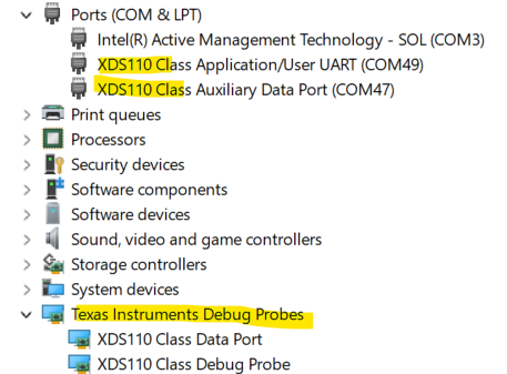
I am using UniFlash and the XDS110 Debug Probe to flash the microcontroller using the JTAG port.
The pin 3 on the U6 JTAG port is connected to ground on my XDS110 probe cable
I keep getting the following error when I request more info about the TIVA TM4C1294NCPDT by clicking on Read Device Info:

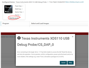
The crystal frequency is set at 8MHz in the settings and utilities.

I get the same error when I try to Load Image.

Please let me know how I can get rid of this error and get UniFlash to be able to recognize the device and be able to flash it. 

  • Hi, I tried the steps in the XDS110 link sent. I am still getting the same error. I am changing the clock rate by lowering it and still same error of JTAG settings need to be changed. 

    I even tried depopulating the U20 on the eval board. That didn't help neither. 

    I would appreciate it if somebody can assist. 

  • Here are the errors we see in code composer:

    The scan-path will be reset by toggling the JTAG TRST signal.
    The controller is the XDS110 with USB interface.
    The link from controller to target is direct (without cable).
    The software is configured for XDS110 features.
    The controller cannot monitor the value on the EMU[0] pin.
    The controller cannot monitor the value on the EMU[1] pin.
    The controller cannot control the timing on output pins.
    The controller cannot control the timing on input pins.
    The scan-path link-delay has been set to exactly '0' (0x0000).


    -----[An error has occurred and this utility has aborted]--------------------


    This error is generated by TI's USCIF driver or utilities.


    The value is '-233' (0xffffff17).
    The title is 'SC_ERR_PATH_BROKEN'.


    The explanation is:
    The JTAG IR and DR scan-paths cannot circulate bits, they may be broken.
    An attempt to scan the JTAG scan-path has failed.
    The target's JTAG scan-path appears to be broken
    with a stuck-at-ones or stuck-at-zero fault.

  • Hi,

      There really isn't any jumpers or modification needed for the board to use an external debug probe. You simply just connect the XDS110 to U6. 

      When you plug the XDS110 to the PC, do you see the probe properly enumerated? Use the Windows Device Manager to make sure it is enumerated correctly. You should see something like below. If you don't see them there is an issue with the probe. Try a different USB port or different PC or new USB cable. Does it make a difference?

      Do you have another LaunchPad you can try? This is to isolate if the problem is with the board. Your log shows that the JTAG scan-chain is broken. 

  • This was resolved. Thank you!