This thread has been locked.

If you have a related question, please click the "Ask a related question" button in the top right corner. The newly created question will be automatically linked to this question.

LP-MSPM0L1306: 2.5V programming using XDS110 Debug probe

Part Number: LP-MSPM0L1306
Other Parts Discussed in Thread: MSPM0L1306

Tool/software:

Good day TI Team,

Summary:

Regarding MSPM0L1306 programming/Debugging with operating voltage 2.5V using TI XDS110 Debug probe.

Please guide regarding connection between TI XDS110 Debug probe and target board with 5 berg pinouts

Details:

We purchased XDS110 Debug probe.

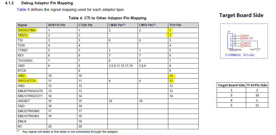
Based on understanding from XDS110 Debug Probe User's Guide,

For programming and debugging (using 2.5V),

We planned to connect target board with TI14 pin adapter of “XDS110 Debug Probe” as below:
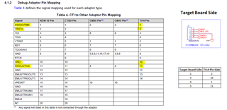
For flashing, 

We are not sure on connection of power supply input of 2.5V and its ground. 

Please validate the above connection and guide us regarding signal connection + power connection between Target board and XDS110 Debug Probe. 

Note:

Placed actual physical connection below for reference:

Thanks

Selvam

  • Please have the actual physical connection with pin number

  • Hello Selvam, 

    Thank you for contacting us. For clarification here, pin 2 of the Target Board indicates MCU 2V5 which I presume refers to 2.5V. Furthermore, on the table you provided, VTREF stands for Voltage Reference which is configured as 2.5 or 1.4 on the MSPM0L1306. Kindly let me know if that provides clarification

    Regards, Jojo

  • Hi Jojo,

    Thanks for the response.

    You are correct, MCU 2V5 is refers to 2.5V.

    Based on input regarding VTREF, updated the connection as below, please validate and correct if any mismatch.

    Also guide us about how to set "Target Voltage-2.5 or 1.4" in Code composer studio while connecting with XDS110 Debug Probe.

    Thanks

    Selvam

  • Hello Selvam, 

    Thank you for your feedback. However, want I wanted in this scenario was just a clarification. Regarding your setup, you have a Target Board and you are using your TI14 pin adapter since the XDS110 probe uses CTI20. 


    Based on the initial pin layout of your target board above, this makes sense. However, if you want to supply power from the XDS110 to the target board's MCU 2V5, you will need to use the aux port of the XDS110 for this. This is referenced in section 3.1.2 Probe Supplied Power of the XDS110 user guide linked below: 
    https://www.ti.com/lit/ug/sprui94/sprui94.pdf?ts=1751472639406&ref_url=https%253A%252F%252Fwww.google.com%252F

    The Probe can supply the target with power from ranges of 1.8V to 3.6V so 2.5V is within range. Kindly let me know if you have further questions or concerns. 

    Regards, Jojo

  • Hi Jojo,

    Thanks for the details.

    So, We need to use two ports (Debug port for signal lines and Aux port for power supply)

    Below is updated connection diagram from understanding, please correct me, if any mismatch.

    Section 3.1.2 of XDS110 user guide shows the options of target voltage setting, not clear about from where we can reach this option,

    like from which menu we can reach this option of "setup power source control", May I have that details?

    Thanks

    Selvam

  • Hello Selvam, 

    Yes, your diagram looks right. Also, just to be clear, the section you should be referencing is 3.1.2.2 since the probe will be used to supply power to the target device. Moreover, you will need to create a target configuration file File -> New File -> "name".ccxml. With this file created in your project, you can configure the device as such. I recommend watching the video below as "probe supplied power" is also configured in this scenario. 

    https://www.youtube.com/watch?v=2999x1oGjao

    Kindly let me know if you have further questions or concerns. 

    Regards, Jojo

  • Hello Selvam, 

    Good day. Just checking in on whether there are any updates on this. If so, kindly let me know. 

    Regards, Jojo