This thread has been locked.

If you have a related question, please click the "Ask a related question" button in the top right corner. The newly created question will be automatically linked to this question.

MSPM0L1306: Timing from starting to do ADC sampling to reach out to ADC interrupt

Part Number: MSPM0L1306
Other Parts Discussed in Thread: SYSCONFIG

Tool/software:

Hi Champ,

I am asking for my customer.

They like to evaluate the timing from starting to do first ADC sampling then reach out to ADC interrupt. To make sure the time to enable ADC interrupt is less than 250us.

The MEM3 result loaded enables the ADC interrupt, and each ADC conversion memory (0~3) configuration's sample period source is configured with sampling timer 1 (30us). And it's software trigger.

(1). What would be total timing calculation from doing ADC 0~3 to reach out to enable ADC interrupt ? would the expert kindly list down the characteristics needed to consider ? 

(2). Would enabling the averaging mode do affect the total timing ?  

Thanks and regards,

Johnny

  • Hello Johnny, 

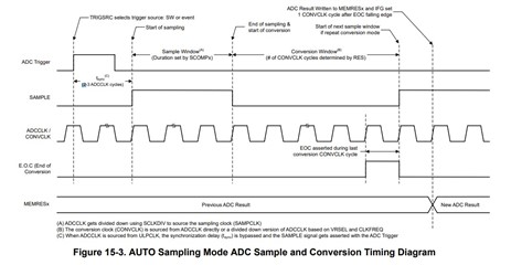
    Thank you for contacting us. To answer your first and second question, the total conversion period for one conversion and control buffer (MEM0 for instance) is pre-calculated and stored in the "ADC Conversion Period", seen in SysConfig, considering you are using Auto mode.

    • The calculation for ADC Conversion time is based on the following factors:

      • ADC Trigger Synchronization Time
        • 3 ADC Clock Cycles are needed for synchronization after the trigger signal is set
        • Note that this synchronization time is bypassed when ULPCLK sources the ADC Clock
      • ADC Sample Time
        • User determined time based on Sample Time 0 (SCOMP0) and Sample Time 1 (SCOMP1) values
      • ADC Conversion Time
        • The number of clock cycles required to perform the conversion
        • Dependent on ADC resolution and device specifics. Refer to the datasheet for specific values.
      • Hardware Accumulation/Averaging
        • When configured, hardware accumulation takes multiple samples back-to-back
    • Calculation Formula:

      • ADC Conversion Period = ADCSyncTime + [(ADCSampleTime + ADCConversionTime) * HWAccumulation]

    Hence, since you are using all four mem registers and it's in sequence, you will need to add each MEM instance value from the "ADC Conversion Period" to get your final result. The diagram for the auto sampling mode and conversion timing can be seen below: 

    This can be found in the Section 15.2.8.1 AUTO Sampling mode of the MSPM0 L-Series 32-MHz Microcontrollers Technical Reference Manual linked below: 

    https://www.ti.com/lit/ug/slau847e/slau847e.pdf

    Kindly let me know if this clarifies it or if there are further questions/concerns. 

    Regards, Jojo

  • Hello Johnny, 

    Hope all is well. Just checking if further clarification is needed on this or not. If so, kindly let me know. 

    Regards, Jojo