Part Number: MSPM0G3507
Tool/software:
Hi, TI expertise
I am kindly asking for help to solve this situation.
Chip model: MSPM0G3507SRHBR [VQFN]
SDK version: 1.00.01.03
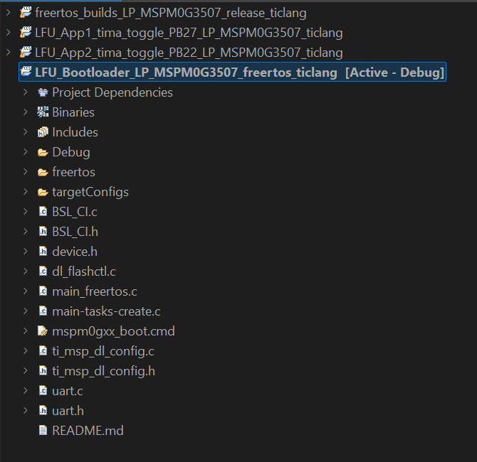
I am trying to use an example from the "MSPM0 Live Firmware Update (LFU) Bootloader Implementation" guide.
First, I flash the Bootloader code into the chip. Then, I used the Python-based PC software provided in the example files. But it cannot identify a UART signal from the chip. When I do test with the MSPM0G3507 launch pad, it works.

In the example bootloader code, UART 0 is defined like this,
/* Defines for UART_0 */
#define UART_0_INST                                                        UART0
#define UART_0_INST_IRQHandler                                  UART0_IRQHandler
#define UART_0_INST_INT_IRQN                                      UART0_INT_IRQn
#define GPIO_UART_0_RX_PORT                                                GPIOA
#define GPIO_UART_0_TX_PORT                                                GPIOA
#define GPIO_UART_0_RX_PIN                                        DL_GPIO_PIN_11
#define GPIO_UART_0_TX_PIN                                        DL_GPIO_PIN_10
#define GPIO_UART_0_IOMUX_RX                                     (IOMUX_PINCM22)
#define GPIO_UART_0_IOMUX_TX                                     (IOMUX_PINCM21)
#define GPIO_UART_0_IOMUX_RX_FUNC                      IOMUX_PINCM22_PF_UART0_RX
#define GPIO_UART_0_IOMUX_TX_FUNC                      IOMUX_PINCM21_PF_UART0_TX
#define UART_0_BAUD_RATE                                                  (9600)
#define UART_0_IBRD_32_MHZ_9600_BAUD                                       (208)
#define UART_0_FBRD_32_MHZ_9600_BAUD                                        (21)
But in our design, we use these pins for UART,

I think this is the problem with UART communication. Help me to change this pin mux configuration. But this example project does not have a "System Configuration" to set up or change any configuration.