This thread has been locked.

If you have a related question, please click the "Ask a related question" button in the top right corner. The newly created question will be automatically linked to this question.

MSPM0C1104: How to configure the config in CCS to enable Manchester encoding for effective transmission and reception.

Part Number: MSPM0C1104

Tool/software:

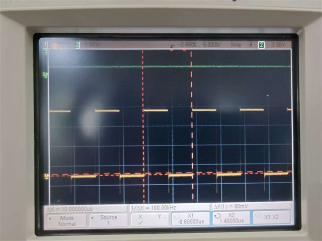
I defined a key command. After clicking the key, the DMA instruction for moving the array will be triggered and output through TIMER_PWM. The communication rate is 5us per bit, with a transition every 5us. Maybe there is a problem with my configuration in CCS_config. I don't know why the waveform I want to send doesn't appear. Instead, a repetitive waveform shows up and the sending doesn't stop. It doesn't end the sending after moving all the data in my array,Could you provide a successful example of sending a 5us pulse change for me to refer to when configuring CCS_Config?

  • ending a 5us pulse change 

    What means with 5us change? You want to generate a PWM with the duty change?

    Can you let me know what the wave result that you want?

  • I use button presses to control the sending of instructions for Manchester communication. I store the instructions 0, 1, 0, 1, 1, 0, 1, 0, 0, 1, 0, 1 in an array for sending. Since a 5us low-level to 5us high-level transition is considered as a high level, and vice versa for a low-level to high-level transition, I want to output different waveforms using PWM. However, the current phenomenon is abnormal. That's it. I hope to achieve the following: when my button is pressed, DMA will transfer the specified waveform from my array to timer_PWM for output at a rate of 100k, and stop sending after the output is complete.

  • I am still not clearly understand what the PWM control will be like. For example 0: means 20% duty cycle PWM with 1 cycle. 1: means 60% duty cycle PWM with 1 cycle. If you only need one cycle PWM signal, I would suggest you to use other methods to realize.

    1. One is to use SPI 

    2. Two is directly control the GPIO. For communication, I would suggest you to use DMA to direclty access the GPIO with a timer help. Here is an example:

    C_G3507_8bitComm.zip

  • void TIMER_0_INST_IRQHandler(void) {
      switch (DL_TimerG_getPendingInterrupt(TIMER_0_INST)) {
      case DL_TIMERG_IIDX_ZERO:
      /* Send encoding program */
        timer_count++;
        if (timer_count == send_buff[array_count]) {
          DL_GPIO_togglePins(GPIO_OPB9000_CAL_PORT, GPIO_OPB9000_CAL_CAL_PIN);
          array_count++;
          if (array_count >= array_len) {
            DL_TimerG_stopCounter(TIMER_0_INST);
          }
        }

        // DL_GPIO_togglePins(GPIO_OPB9000_CAL_PORT, GPIO_OPB9000_CAL_CAL_PIN);
      
        break;
      default:
        break;
      }
    }
    Just as I wrote, however, currently I'm using the timer's interrupt to periodically toggle the IO port. I control the duration of the IO port toggle to achieve the waveform I want, such as a 5us high level to a 5us low level, and it can freely toggle. So, there is a drawback to this approach, which is that the toggle speed of the IO port is not sufficient. Therefore, I need to use DMA to transfer the data to timer_PWM. This way, the CPU does not need to be involved, and it should enable faster communication. What I'm doing at this moment is equivalent to simulating a DMA. I don't know how to configure DMA in CCS to transfer the data in my array to achieve different high and low level toggles,thank you.
  • Can you refer to the code example I shared with you. Then you don't need to use interrupt.