


Part Number: MSPM0L1306
Other Parts Discussed in Thread: SYSCONFIG
Tool/software:
Hi.
I have a firmware project targeting the MSPM0L1306. This firmware reconnects certain MCU pins to different MCU peripherals at different times. For example, under certain conditions, a MCU pin behaves as a SPI peripheral pin, an other times its an interrupt GPIO with interrupt capability. I'm capable of changing the functionality of the pins, and serial interfaces (SPI, I2C, etc) work without issue, but capturing input interrupts is being more problematic.
To simplify the problem, I've generated a minimum working example. Here all I want is to detect when the GPIO ISR is called when a rising edge condition is detected on a interrupt capable input pin. No pin capabilities are inplemented, nor low power mode states are used.
Below is the content of the sysconfig file of my MWE:
/**
 * These arguments were used when this file was generated. They will be automatically applied on subsequent loads
 * via the GUI or CLI. Run CLI with '--help' for additional information on how to override these arguments.
 * @cliArgs --device "MSPM0L130X" --part "Default" --package "VQFN-32(RHB)" --product "mspm0_sdk@2.05.01.01"
 * @v2CliArgs --device "MSPM0L1306" --package "VQFN-32(RHB)" --product "mspm0_sdk@2.05.01.01"
 * @versions {"tool":"1.24.0+4150"}
 */

/**
 * Import the modules used in this configuration.
 */
const GPIO          = scripting.addModule("/ti/driverlib/GPIO", {}, false);
const GPIO1         = GPIO.addInstance();
const SYSCTL        = scripting.addModule("/ti/driverlib/SYSCTL");
const ProjectConfig = scripting.addModule("/ti/project_config/ProjectConfig");

/**
 * Write custom configuration values to the imported modules.
 */
GPIO1.$name                         = "GPIO_GRP_EXAMPLE_TEST";
GPIO1.associatedPins.create(3);
GPIO1.associatedPins[0].direction   = "INPUT";
GPIO1.associatedPins[0].fastWakeEn  = true;
GPIO1.associatedPins[0].interruptEn = true;
GPIO1.associatedPins[0].polarity    = "RISE";
GPIO1.associatedPins[0].$name       = "PIN_INTERRUPT_CAPABLE_INPUT";
GPIO1.associatedPins[1].$name       = "PIN_INTERRUPT_ACTIVITY";
GPIO1.associatedPins[1].pin.$assign = "PA1";
GPIO1.associatedPins[2].$name       = "PIN_CONTROL";

const Board                       = scripting.addModule("/ti/driverlib/Board", {}, false);
Board.peripheral.$assign          = "DEBUGSS";
Board.peripheral.swclkPin.$assign = "PA20";
Board.peripheral.swdioPin.$assign = "PA19";

SYSCTL.peripheral.$assign = "SYSCTL";

ProjectConfig.migrationCondition = true;

/**
 * Pinmux solution for unlocked pins/peripherals. This ensures that minor changes to the automatic solver in a future
 * version of the tool will not impact the pinmux you originally saw.  These lines can be completely deleted in order to
 * re-solve from scratch.
 */
GPIO1.associatedPins[0].pin.$suggestSolution = "PA0";
GPIO1.associatedPins[2].pin.$suggestSolution = "PA2";
Here I've instantiated 3 GPIO pins:
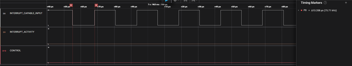
- PIN_INTERRUPT_CAPABLE_INPUT is the interrupt capable input pin that should trigger interrupts on rising edges
- PIN_INTERRUPT_ACTIVITY is an output pin I use to indicate when I'm inside the ISR
- PIN_CONTROL is an output pin I use to signal an external device to start generating activity on PIN_INTERRUPT_CAPABLE_INPUT
The main program is as follows:
#include "ti_msp_dl_config.h"

int main(void)
{
    SYSCFG_DL_init();

    NVIC_EnableIRQ(GPIO_GRP_EXAMPLE_TEST_INT_IRQN);

    while (1) {
    }
}

void GROUP1_IRQHandler(void)
{
    DL_GPIO_setPins(GPIO_GRP_EXAMPLE_TEST_PORT, GPIO_GRP_EXAMPLE_TEST_PIN_INTERRUPT_ACTIVITY_PIN);

    DL_GPIO_clearPins(GPIO_GRP_EXAMPLE_TEST_PORT, GPIO_GRP_EXAMPLE_TEST_PIN_INTERRUPT_ACTIVITY_PIN);
}
Pin configuration is done by SYSCFG_DL_init(). All my ISR does is, when entered, sets PIN_INTERRUPT_ACTIVITY, and then inmediately clears it.
If I run this software with -O0 optimizations, I can see that PIN_INTERRUPT_ACTIVITY toggles on rising edges of PIN_INTERRUPT_CAPABLE_INPUT.

If I run the same software with -O2 optimizations, PIN_INTERRUPT_ACTIVITY does not toggle on PIN_INTERRUPT_CAPABLE_INPUT rising edges.
I am working with CCS 12.8.1, MSPM0 SDK 2.5.1 and Sysconfig 1.24. I wasn't expecting this behaviour. How can I make sure that the GPIO ISR is called on rising edge GPIO inputs with -O2 or -O3 optimizations?
Thanks
