This thread has been locked.

If you have a related question, please click the "Ask a related question" button in the top right corner. The newly created question will be automatically linked to this question.

AM2612: Timer Interrupt Period is longer than the expectatoin

Part Number: AM2612
Other Parts Discussed in Thread: LP-AM261, SYSCONFIG

Tool/software:

Hi,


The customer is now evaluating AM2612 by using LP-AM261.


They’re considering to connect 25MHz crystal oscillator to EXT_REFCLK0.

This pin of EXT_REFCLK0 can be input up to 100MHz. Correct ?


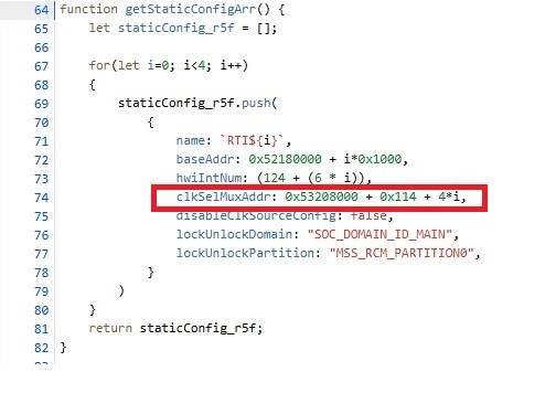
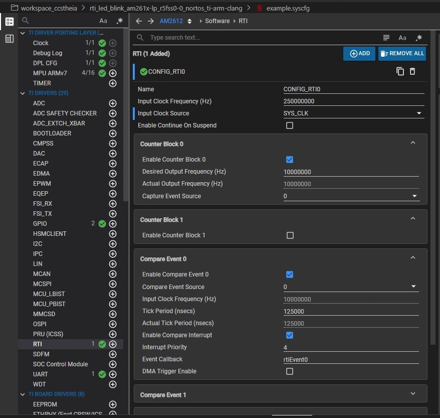
They’re evaluating the timer interrupt with the following configuration, and observing the period of timer interrupt by using the oscilloscope. It’ll be 125us period of timer interrupt.


When AM2612 is booted up with DEVBOOT mode, they can observe 125us period of timer interrupt as they expected.

However, it’ll be 1,250us when it is booted up with OSPI BOOT mode. It is 1,000 times longer period than they expected.


Do you have any solution to solve this issue ?


Thanks and regards,

Hideaki

  • Hello,

    For the timer interrupt period, is that continuous or just when the device is first booted? As in, have you observed it interrupting multiple times in a row at this longer time without resetting anything?

    Regards,

    Susan

  • Hi Susan,

    Thank you for your reply.

    This issue occurred continuously after booted. Every period became 1,250us even they set 125us.

    Please give the customer any advice.

    Thanks and regards,
    Hideaki

  • Hi,

    Could we have any response ?

    Thanks and regards,

    Hideaki

  • However, it’ll be 1,250us when it is booted up with OSPI BOOT mode. It is 1,000 times longer period than they expected.

    Hi Matsumoto-San,

    Apologies for a delayed response. Let me run some tests and get back here.

    Also, for the current test with 125us period, they are using SYS_CLK and not EXT clock right?

    This pin of EXT_REFCLK0 can be input up to 100MHz. Correct ?

    As per the TRM table 13-303, EXT_REFCLK for RTI can be 100MHz.

    Regards,
    Shaunak

  • Hi Matsumoto-San,

    I tested the following on AM261x-LP E2 board (in both DEV boot mode with GEL scripts configured, and in OSPI boot mode with SBL Null flashed)

    1. RTI Led blink out-of-box application

    2. Set a breakpoint at the rtiEvent0() function.

    3. Profile using the built-in CCS clock to see the time period between the RTI ISR being hit

    Though the CCS clock is not very accurate (as much as an oscilloscope would be), it was still approximately around 125us that I observed.

    Can you please help me understand the following details:

    1. Are you using any default RTI SDK example or is it a custom software. If a custom software, can you share the application with me as well (so I can test and verify the same on my end)

    2. What exacts pins are you probing on the LP?

    3. Are there any other interrupts in the system (other than the Clock tick interrupt and the RTI interrupt)?

    Regards,
    Shaunak

  • Hi Shaunak,

    Thank you for testing it on your side as well. As I'm now asking your questions to the customer, please wait for a while.

    they are using SYS_CLK and not EXT clock right?

    Yes, they're using SYS_CLK.

    Thanks and regards,

    Hideaki

  • Hi Shaunak,

    I sent the customer's feedbacks to your questions off-line via e-mail. Could you please check it. The example project has been sent, too.

    Thanks and regards,

    Hideaki

  • Hi Matsumoto-San,

    Yes I have received the application, I'm currently running some tests for this. I'll get back with some update before the end of the day.

    Regards,
    Shaunak

  • Hi Shaunak,

    Did you get any result ?  Could you please update the status ?

    Thanks and regards,

    Hideaki

  • Hi Shaunak,

    Thank you so much for your support off-line.

    Here's the feedback which I received.

    -------------------------------------------------------------------------------------

    I have root-caused the issue. Below is the issue summary and fix:

    1. The RTI configuration for RTI instances  was being done incorrectly by the syscfg auto-generated code. Specifically, the auto-generated code used an address which was incorrect, so the default clock source (WUCPUCLK of 25MHz was being used). Even though we had configured it to be 250MHz, since the clock source selected was 10x lower in frequency, the time period was 10x higher (125us to 1250us)
    2. The below highlighted line in the image (in red) is calculating the address incorrectly in mcu_plus_sdk\source\sysconfig\drivers\.meta\rti\soc\rti_am261x.syscfg.js

    This line number 74 needs to be updated to:

    clkSelMuxAddr: 0x53208000 + 0x140 + 4*i,               


    After making the above change, please re-open your syscfg, check the configuration, save it and re-build your application.

    Then check the ti_drivers_config.h file generated and verify that the CONFIG_RTI0_CLOCK_SRC_MUX_ADDR  is defined as 0x53208144h and not 0x53208118u


    The issue was not observed in gel scripts based DEV Bootmode approach because we set all the clock sources to be SYS_CLK by default at correct addresses, and in-case of SBL-OSPI, post SBL we relied on application to do the RTI1 configuration, which was done at incorrect address.

    I have locally tested with the above change and am able to see a consistent 125us gap between interrupts now in both DEV as well as OSPI boot-mode. I’ll raise a bug and get this fixed in the MCU_PLUS_SDK as well.

    -------------------------------------------------------------------------------

    Thanks and regards,

    Hideaki

  • Hi Hideaki,

    The above solution resolved the customer issue right?

    Regards,
    Shaunak