


Part Number: AM263P4
Other Parts Discussed in Thread: SYSCONFIG
Tool/software:
Hey Experts,
ive some question regarding the synchronisation between SDFM and resolver module.
As SW i am using:
CCS 12.8.1.00005
SDK 10_00_00_35
We wanna implement a motor control. Therefore its important to have current and angle measurement with a minimum of delay between each other.
The currents are measured with SDFM module. I can trigger a measurement with my PWM. Then i get a data rdy interrupt, where i know i received new data.
So far, so good.
With the resolver inteface its not that easy. I can enable a sync to PWM for excitation PWM in systemconfig and i imagine the resolver value is sampled at the maximum of excitation PWM. Am i rigth with this?
This means i don't trigger a measurment of resolver value directly but 25µs (if excitation PWM freq is 20kHz) later.
Also i don't have any data rdy interrupt. So iam not sure when exactly i have new data.
I tried to check examples to get a better understanding but this gets me confused even more.
I'm relating to this example: https://software-dl.ti.com/mcu-plus-sdk/esd/AM263PX/10_00_00_35/exports/docs/api_guide_am263px/EXAMPLES_DRIVERS_RESOLVER_ANGLE_SPEED.html
It says: The ADC SoC start Delay is set at 20, i.e., 20*1250nS +30nS or, 25.030 uS. First of all i cant find this configuration in the related sysconfig. There it's set to zero:
then it implies that i have to set the sample timing manually? I thought the ideal sampling time module is in charge of the sampling time?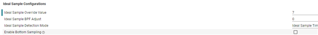
What is the Ideal Sample Overwrite value of 7 used for?
Summarized iam not sure when the resolver sampling gets started and when it has finished.
Moreover i don't know how old is the resolver value when i sampled it? There is no information about the phase delay of the bandpassfilter you can apply.
I think this synchronisation of currents and angle is a common task for motor control. Maybe there is already an example or application note related to this topic?
Best regards
Marcel
