This thread has been locked.

If you have a related question, please click the "Ask a related question" button in the top right corner. The newly created question will be automatically linked to this question.

TMDS243EVM: PCIe example does not work (TMDS243EVM ↔︎ TMDS243EVM)

Part Number: TMDS243EVM
Other Parts Discussed in Thread: TMDS64EVM

Tool/software:

Hi, experts.

I have two TMDS243EVM and am running PCIe example code.

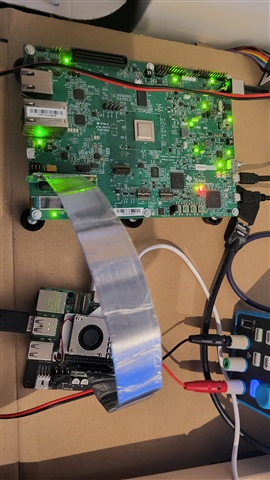
I connected the PCIe cable in the picture below to the PCIe connectors of the two boards

and downloaded pcie_benchmark_ep and pcie_benchmark_rc respectively and ran it,

but RC didn't respond(output).

No matter what I change the PCIe mode on both boards to, the example code doesn't work.
Certain settings cause the board to reset.
What should I do?
Is there something I'm missing?

Best Regards,

  • Hi,

    the pcie_benchmark_rc/ep examples are broken since MCU+ SDK 09.02.01, see the known issues in the MCU+ SDK release notes:

    https://software-dl.ti.com/mcu-plus-sdk/esd/AM64X/latest/exports/docs/api_guide_am64x/RELEASE_NOTES_11_01_00_PAGE.html

    The PCIe driver was extended in that release to support use with an x86 RC (Windows or Linux), but most of the existing examples weren't adapted.

    The only example that should work is pcie_msi_irq_ep/rc.

    In my opinion the J34 jumper should be disconnected on both RC and EP, and J35 doesn't matter for a TMDS243EVM<->TMDS243EVM setup.

    Power-up the EP first, load the application, and let it run, then power-up the RC, load the application, and let it run.

    If you get this:

    Endpoint Device ID: FFFFX
    Endpoint Vendor ID: 1X

    Modify the code in pcie_msi_irq_rc_main that reads these IDs:

            /*
             * retry reading vendor and device ID in case of CRS completion
             */
            do {
                status = Pcie_getVendorId(gPcieHandle[CONFIG_PCIE0], PCIE_LOCATION_REMOTE, &vndId, &devId);
            } while (status == SystemP_SUCCESS && vndId == 0x0001 && devId == 0xffff);

    Regards,

    Dominic

  • The RC example seems to be working normally.

    When I connect another pcie device (ex. NIC), the Device/Vendor ID of the EP is output normally.

    But the EP example doesn't seem to be working properly.

    When I put the pcie_msi_irq_ep example code and connect the PCIE to a RC-powered board,

    the PCIE_waitLinkUp (object->handle) code doesn't 'link up' and it's circling the while statement.

    (sdk version : 11.01.00.17)

    (J34 is not connected. Does not work regardless of the connection of PCIE_SERDES_REFCLK0_P(REFCLK+), PCIE_SERDES_REFCLK0_N(REFCLK-) to the cable)


    What should I do?

    Does that example code only work if you solder a specific resistor like R661 etc?

  • 4.1 Common Setup for LINUX and WIN, 4.2 Linux Driver, 4.3 Test Application Usage, 4.4 Setup Steps for LINUX PC
    (ref. AM64x and AM243x: MCU+ SDK-Based PCIe End Point)
     
    I modified the kernel of Raspberry Pi CM5 by referring to the contents in the above document
    and connected it with PCIe cable (CM5 i/o board Left right arrow TMDS243EVM).
    but the pcie enumeration is not performed normally with the following results in cm5.
     
  • Hi,

    When I put the pcie_msi_irq_ep example code and connect the PCIE to a RC-powered board,

    the PCIE_waitLinkUp (object->handle) code doesn't 'link up' and it's circling the while statement.

    is this using pcie_msi_irq_ep/rc on two AM24x/AM64x EVMs, or some other RC?

    (J34 is not connected. Does not work regardless of the connection of PCIE_SERDES_REFCLK0_P(REFCLK+), PCIE_SERDES_REFCLK0_N(REFCLK-) to the cable)


    What should I do?

    Does that example code only work if you solder a specific resistor like R661 etc?

    The pcie_msi_irq example should work with an unmodified EVM (e.g. leave R661 and the other resistors mentioned in the pcie_enumerate_ep example as-is). In that case your cable should NOT connect RefClk.

    If you've modified an EVM for use as an EP according to the pcie_enumerate_ep instructions, your PCIe cable MUST have RefClk connected.

    4.1 Common Setup for LINUX and WIN, 4.2 Linux Driver, 4.3 Test Application Usage, 4.4 Setup Steps for LINUX PC
    (ref. AM64x and AM243x: MCU+ SDK-Based PCIe End Point)

    The host driver example is only intended to be used with x86 based RCs:

    The main reason is the need for an IOMMU that allows the example as a user space application to map DMA buffers via VFIO. It is possible to modify the example to use only 4 KB DMA buffers, so that it can be run on an ARM based RC without an IOMMU, too. I've successfully used the example on an AM64x Linux based RC.

    Regards,

    Dominic

  • We flashed the pcie_msi_irq_ep and pcie_msi_irq_rc examples onto two separate TMDS243EVM boards and connected them via PCIe,

    but the communication did not work as expected.


    Our ultimate goal is to establish PCIe communication between a Raspberry Pi CM5 (as RC) and the AM2431ALV (as EP).


    Are there any recommended approaches or example projects better suited for this configuration?

  • Hi,

    I can try and see if I find some time later today to verify pcie_msi_irq_ep/rc with SDK 11.01.

    Regarding your ultimate goal, pcie_enumerate_ep is your best option, but you need to modify the example to use a smaller DMA buffer of only 4KB. Have you been able to enumerate the AM24x in that setup? Your lspci output shows only RPi components.

    The bus/device/function you used doesn't make a lot of sense. The example documentation explains the necessary steps:

    If you don't see the Cadence device then your setup isn't working at all.

    Regards,

    Dominic

  • Hi,

    We modified the TMDS243EVM board as shown in the reference image (our understanding is that this configuration allows the AM243 to receive the RefClk provided by the RPi CM5 — is that correct?).


    After flashing the pcie_enumerate_ep example and connecting the PCIe link, we rebooted the RPi CM5, but it seems that the link does not come up. We suspect that enumeration is not happening under this setup.

    Since we currently have only one TMDS243EVM available, we would like to check whether the PCIe module on the AM243 is functioning properly.
    At the register level, which specific registers should we check to verify that the PCIe module is correctly enabled?

    Also, even after reducing the DMA buffer size on the RPi CM5, enumeration still fails. What potential issues should we consider in this case?

  • We modified the TMDS243EVM board as shown in the reference image (our understanding is that this configuration allows the AM243 to receive the RefClk provided by the RPi CM5 — is that correct?).

    Yes.

    Can you verify that your cable connects RefClk 1:1 and connects TX+- on one end to RX+- on the other end and vice versa?

    After flashing the pcie_enumerate_ep example and connecting the PCIe link, we rebooted the RPi CM5, but it seems that the link does not come up. We suspect that enumeration is not happening under this setup.

    Since we currently have only one TMDS243EVM available, we would like to check whether the PCIe module on the AM243 is functioning properly.
    At the register level, which specific registers should we check to verify that the PCIe module is correctly enabled?

    Can you try the following steps:

    • Power off EP and RC
    • Power on EP, wait for the pcie_enumerate_ep example to start
    • Verify that the EP outputs "PCIe: EP initialized and waiting for link"
    • Power on RC, wait for Linux to boot
    • Verify that the EP outputs "PCIe: link detected. PCIe Link Parameter: PCIe Gen1 with 2.5 GT/s speed, Number of Lanes: 1"
    • Check whether lspci sees the Cadence device.

    If the EP is stuck checking for a link then no, enumeration can't proceed. The link is the very first requirement.

    Also, even after reducing the DMA buffer size on the RPi CM5, enumeration still fails. What potential issues should we consider in this case?

    That doesn't affect enumeration. The DMA buffer size only affects the Linux RC example program.

    Regards,

    Dominic

  • I've just tested this myself using a RPi5 with a "GeeekPi P02 PCIe Slot for Raspberry Pi 5" and a TMDS64EVM, and the pcie_enumerate_ep example gets enumerated by the RPi5 without problems:

    • Power off AM64x, RPi5
    • Use SD-Card with sbl_null.release.hs_fs.tiimage from mcu_plus_sdk_am64x_11_01_00_17 (tiboot3.bin)
    • Power on AM64x
    • Build, load and run pcie_enumerate_ep example
    • Power on RPi5

    On the AM64x terminal I'm seeing this output:

    PCIe: EP initialized and waiting for link
    PCIe: link detected
    PCIe link parameter: PCIe Gen2 with 5.0 GT/s speed, number of lanes: 1
    EP is in D0 state
    PCIe: signaling APPL ready
    APPL: pcie ready

    On a Linux shell I can see the AM64x:

    vmaster@krikkit:~ $ lspci
    0000:00:00.0 PCI bridge: Broadcom Inc. and subsidiaries Device 2712 (rev 21)
    0000:01:00.0 Unassigned class [ffff]: Cadence Design Systems, Inc. Device 0100
    0001:00:00.0 PCI bridge: Broadcom Inc. and subsidiaries Device 2712 (rev 21)
    0001:01:00.0 Ethernet controller: Device 1de4:0001
    
    vmaster@krikkit:~ $ sudo lspci -vvv -s 0000:01:00.0
    0000:01:00.0 Unassigned class [ffff]: Cadence Design Systems, Inc. Device 0100
            Subsystem: Cadence Design Systems, Inc. Device 0000
            Control: I/O- Mem- BusMaster- SpecCycle- MemWINV- VGASnoop- ParErr- Stepping- SERR- FastB2B- DisINTx-
            Status: Cap+ 66MHz- UDF- FastB2B- ParErr- DEVSEL=fast >TAbort- <TAbort- <MAbort- >SERR- <PERR- INTx-
            Region 0: Memory at 1b00200000 (32-bit, non-prefetchable) [disabled] [size=32K]
            Region 1: Memory at 1b00000000 (32-bit, prefetchable) [disabled] [size=1M]
            Region 2: Memory at 1b00100000 (64-bit, non-prefetchable) [disabled] [size=1M]
            Capabilities: [80] Power Management version 3
                    Flags: PMEClk- DSI- D1+ D2- AuxCurrent=0mA PME(D0+,D1+,D2-,D3hot+,D3cold-)
                    Status: D0 NoSoftRst+ PME-Enable- DSel=0 DScale=0 PME-
            Capabilities: [90] MSI: Enable- Count=1/16 Maskable- 64bit+
                    Address: 0000000000000000  Data: 0000
            Capabilities: [b0] Null
            Capabilities: [c0] Express (v2) Endpoint, MSI 00
                    DevCap: MaxPayload 128 bytes, PhantFunc 0, Latency L0s <1us, L1 <1us
                            ExtTag- AttnBtn- AttnInd- PwrInd- RBE+ FLReset- SlotPowerLimit 0W
                    DevCtl: CorrErr+ NonFatalErr+ FatalErr+ UnsupReq+
                            RlxdOrd+ ExtTag- PhantFunc- AuxPwr- NoSnoop+
                            MaxPayload 128 bytes, MaxReadReq 512 bytes
                    DevSta: CorrErr- NonFatalErr- FatalErr- UnsupReq- AuxPwr- TransPend-
                    LnkCap: Port #0, Speed 5GT/s, Width x1, ASPM L1, Exit Latency L1 <8us
                            ClockPM- Surprise- LLActRep- BwNot- ASPMOptComp+
                    LnkCtl: ASPM Disabled; RCB 64 bytes, Disabled- CommClk+
                            ExtSynch- ClockPM- AutWidDis- BWInt- AutBWInt-
                    LnkSta: Speed 5GT/s, Width x1
                            TrErr- Train- SlotClk+ DLActive- BWMgmt- ABWMgmt-
                    DevCap2: Completion Timeout: Range B, TimeoutDis+ NROPrPrP- LTR+
                             10BitTagComp- 10BitTagReq- OBFF Via message, ExtFmt+ EETLPPrefix+, MaxEETLPPrefixes 1
                             EmergencyPowerReduction Not Supported, EmergencyPowerReductionInit-
                             FRS- TPHComp- ExtTPHComp-
                             AtomicOpsCap: 32bit- 64bit- 128bitCAS-
                    DevCtl2: Completion Timeout: 50us to 50ms, TimeoutDis- LTR+ 10BitTagReq- OBFF Disabled,
                             AtomicOpsCtl: ReqEn-
                    LnkCap2: Supported Link Speeds: 2.5-5GT/s, Crosslink- Retimer- 2Retimers- DRS-
                    LnkCtl2: Target Link Speed: 5GT/s, EnterCompliance- SpeedDis-
                             Transmit Margin: Normal Operating Range, EnterModifiedCompliance- ComplianceSOS-
                             Compliance Preset/De-emphasis: -6dB de-emphasis, 0dB preshoot
                    LnkSta2: Current De-emphasis Level: -6dB, EqualizationComplete- EqualizationPhase1-
                             EqualizationPhase2- EqualizationPhase3- LinkEqualizationRequest-
                             Retimer- 2Retimers- CrosslinkRes: unsupported
            Capabilities: [100 v2] Advanced Error Reporting
                    UESta:  DLP- SDES- TLP- FCP- CmpltTO- CmpltAbrt- UnxCmplt- RxOF- MalfTLP- ECRC- UnsupReq- ACSViol-
                    UEMsk:  DLP- SDES- TLP- FCP- CmpltTO- CmpltAbrt- UnxCmplt- RxOF- MalfTLP- ECRC- UnsupReq- ACSViol-
                    UESvrt: DLP+ SDES+ TLP- FCP+ CmpltTO- CmpltAbrt- UnxCmplt- RxOF+ MalfTLP+ ECRC- UnsupReq- ACSViol-
                    CESta:  RxErr- BadTLP- BadDLLP- Rollover- Timeout- AdvNonFatalErr-
                    CEMsk:  RxErr- BadTLP- BadDLLP- Rollover- Timeout- AdvNonFatalErr+
                    AERCap: First Error Pointer: 00, ECRCGenCap+ ECRCGenEn- ECRCChkCap+ ECRCChkEn-
                            MultHdrRecCap- MultHdrRecEn- TLPPfxPres- HdrLogCap-
                    HeaderLog: 00000000 00000000 00000000 00000000
            Capabilities: [150 v1] Device Serial Number 00-00-00-00-00-00-00-00
            Capabilities: [160 v1] Power Budgeting <?>
            Capabilities: [1b8 v1] Latency Tolerance Reporting
                    Max snoop latency: 0ns
                    Max no snoop latency: 0ns
            Capabilities: [1c0 v1] Dynamic Power Allocation <?>
            Capabilities: [300 v1] Secondary PCI Express
                    LnkCtl3: LnkEquIntrruptEn- PerformEqu-
                    LaneErrStat: 0
            Capabilities: [400 v1] Vendor Specific Information: ID=0001 Rev=1 Len=010 <?>
            Capabilities: [440 v1] Process Address Space ID (PASID)
                    PASIDCap: Exec+ Priv+, Max PASID Width: 14
                    PASIDCtl: Enable- Exec- Priv-
            Capabilities: [4c0 v1] Virtual Channel
                    Caps:   LPEVC=0 RefClk=100ns PATEntryBits=1
                    Arb:    Fixed- WRR32- WRR64- WRR128-
                    Ctrl:   ArbSelect=Fixed
                    Status: InProgress-
                    VC0:    Caps:   PATOffset=00 MaxTimeSlots=1 RejSnoopTrans-
                            Arb:    Fixed- WRR32- WRR64- WRR128- TWRR128- WRR256-
                            Ctrl:   Enable+ ID=0 ArbSelect=Fixed TC/VC=ff
                            Status: NegoPending- InProgress-
                    VC1:    Caps:   PATOffset=00 MaxTimeSlots=1 RejSnoopTrans-
                            Arb:    Fixed- WRR32- WRR64- WRR128- TWRR128- WRR256-
                            Ctrl:   Enable- ID=1 ArbSelect=Fixed TC/VC=00
                            Status: NegoPending- InProgress-
                    VC2:    Caps:   PATOffset=00 MaxTimeSlots=1 RejSnoopTrans-
                            Arb:    Fixed- WRR32- WRR64- WRR128- TWRR128- WRR256-
                            Ctrl:   Enable- ID=2 ArbSelect=Fixed TC/VC=00
                            Status: NegoPending- InProgress-
                    VC3:    Caps:   PATOffset=00 MaxTimeSlots=1 RejSnoopTrans-
                            Arb:    Fixed- WRR32- WRR64- WRR128- TWRR128- WRR256-
                            Ctrl:   Enable- ID=3 ArbSelect=Fixed TC/VC=00
                            Status: NegoPending- InProgress-
            Capabilities: [900 v1] L1 PM Substates
                    L1SubCap: PCI-PM_L1.2+ PCI-PM_L1.1+ ASPM_L1.2+ ASPM_L1.1+ L1_PM_Substates+
                              PortCommonModeRestoreTime=255us PortTPowerOnTime=26us
                    L1SubCtl1: PCI-PM_L1.2- PCI-PM_L1.1- ASPM_L1.2- ASPM_L1.1-
                               T_CommonMode=0us LTR1.2_Threshold=287744ns
                    L1SubCtl2: T_PwrOn=26us
            Capabilities: [a20 v1] Precision Time Measurement
                    PTMCap: Requester:+ Responder:- Root:-
                    PTMClockGranularity: Unimplemented
                    PTMControl: Enabled:- RootSelected:-
                    PTMEffectiveGranularity: Unknown
    

    I'm using a AM64x EVM, but apart from the A53 cores that are unused in this case, the AM64x and the AM243x EVM should be identical. The cable I'm using is a Adex Electronics PE-FLEX1-G2.MMCX-12-TI1. In this case the cable did NOT connect RefClk and the AM64x EVM was NOT modified. If you modified the the EVM, you need a cable that connects RefClk.

    Regards,

    Dominic

  • Did you set VFIO, IOMMU differently to rebuild the RPi5 kernel?
    I would appreciate it if you could answer what settings you set when building the kernel.

  • That was using a default kernel. I didn't run the example, only enumeration. For that kernel settings about IOMMU and VFIO don't matter.

    Are you seeing the same results up to this point?

  • No. Logs are not output.

    I did what you said, but it didn't work.

  • Then you need to verify your cable. There are cables that connect the data lines 1:1 and others that cross the data lines. You need crossed data lines, where the receiver goes to the transmitter and vice versa. Do you have a datasheet for your cable? 

  • I couldn't find the schematic of the cable I have. Can I see the schematic of PE-FLEX1-G2.MMCX-12-TI1? I looked it up and it doesn't seem to be provided. Thank you for your quick response.

  • The cable I have, A16, A17 matches the A16, A17 on the other side, and B14, B15 matches the B14, B15 on the other side. Is this the right cable to cross?

  • No,  you need a cable that connects B14/15 to A16/17 and vice versa.

  • After modifying the cable as you mentioned, the pcie_msi_irq_rc/ep example is done normally.

    However, similarly, the pcie_enumerate_ep example does not output the log even if you do as you said.

  • Is AM243 supported for automatic inversion for P/N polarity?

  • I'm not sure what you're saying here.

    You're not getting the PCIe link detected output on the AM24x terminal when running pcie_enumerate_ep with the RPi RC?

    About polarity inversion I don't know, maybe someone from ti can answer that question.