Part Number: TMS570LC4357
Tool/software:
Hi, Gundavarapu
I have several questions about the ecc functionality of flash.
1. flash ecc is an error correction mechanism for flash data inversion, are spi ecc, sci ecc is the same?
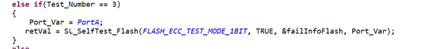
2. flash ecc can be tested by the following method, which describes the CPU error handler can catch the error, could you please explain how to know ECC error occurs? Only by reading the FEDAC_GBLSTATUS register?


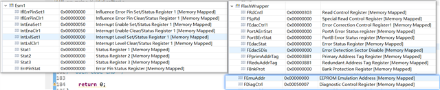
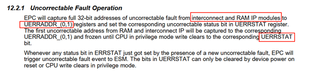
3. When an ECC error occurs, how do you know where it occurred?