This thread has been locked.

If you have a related question, please click the "Ask a related question" button in the top right corner. The newly created question will be automatically linked to this question.

AM2434: new version(CCS 20.2.0) PCIE issue

Part Number: AM2434
Other Parts Discussed in Thread: SYSCONFIG, DP83826E

Tool/software:

Hi Ti Expert,

  My CCS version is CCS 20.2.0,  and SDK is ind_comms_sdk_am243x_11_00_00_08.

  Our design is AM243x + Altera FPGA using PCIE to communicate. MCU is RC and FPGA is EP.

  Following the demo from SDK, pcie_buf_transfer_rc(C:\ti\ind_comms_sdk_am243x_11_00_00_08\mcu_plus_sdk\examples\drivers\pcie\pcie_buf_transfer\pcie_buf_transfer_rc\am243x-evm), we developed our own PCIE project.

  In the old version of CCS 12.4 and SDK 9.2 our project work well, both reading and writing.

  But when I updated to the new version CCS and SDK, our project cannot work for reading and always stuck here,

  The following are the major code of our projects and the screen shot of the old and new projects.

int main(void)

{

       uint32_t * test = (uint32_t *)(0x68000000U + 0x01000000U);

       uint32_t read_test = 0;

       System_init();

       Board_init();

       Drivers_open();

       HAL_PCIE_fpgaInit(gPcieHandle[CONFIG_PCIE0]);


       *(test+0) = 0x1f;  // writing

       *(test+0) = 0x0;    // writing

       *(test+0) = 0x1;    // writing


       read_test = *(test+0x140/4);   //reading, Isse is here


       Board_deinit();

       System_deinit();

       return 0;


}


//This is my init function for fpga-PCIE.


int32_t HAL_PCIE_fpgaInit(Pcie_Handle handle)

{

       int32_t status = SystemP_SUCCESS;

       pcieHandle = handle; //gPcieHandle[CONFIG_PCIE0]


       //Drivers_open(); // if this driver is the only one in this project, need this line

       //Board_driversOpen(); // if this driver is the only one in this project, need this line


       status = Pcie_getVendorId(pcieHandle, PCIE_LOCATION_REMOTE, &vndId, &devId);


       if (SystemP_SUCCESS != status)

       {

              return status;

       }


       status = pcieFpgaSetStatusCmd(pcieHandle);


       if (SystemP_SUCCESS != status)

       {

              return status;

       }


       status = pcieFpgaEpBar1Cfg(pcieHandle);


       if (SystemP_SUCCESS != status)

       {

              return status;

       }


       status = pcieWriteDevStatCtrlReg(pcieHandle);


       if (SystemP_SUCCESS != status)

       {

              return status;

       }

       pcie_initialized_indicating = 1;

       return status;


}


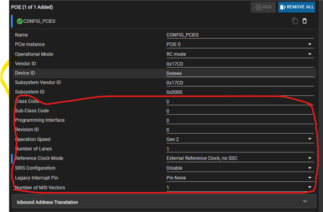
sysconfig for old project

sysconfig for new project

Please help me with this,

BR,

Chunyang

  • Hi Chunyang,

    But when I updated to the new version CCS and SDK, our project cannot work for reading and always stuck here,

    Have you tried running the default example from SDK v11.0 without any modification?

    Does the above example works with CCS v12.8.1 and ind_comms_sdk_am243x_11_00_00_08? This details are required to ensure the example does not break because of CCS upgrade.

    Regards,

    Tushar

  • Hi Chunyang,

    is this on a TMDS243 EVM? Or some custom hardware?

    If it is a custom hardware, how is the reference clock distributed? Is this an input from a common clock source to both the AM24x and the FPGA, or are you expecting the AM24x to generate the clock for the FPGA?

    From SDK 09.02.00 to 09.02.01, there have been changes to the PCIe driver. They were mostly limited to the EP part, but one change that also affects the RC functionality is the reference clock. On TI evaluation boards the reference clock is an input that is driven by an on-board clock generator, hence the default to "external reference".

    Regards,

    Dominic

  • Have you tried running the default example from SDK v11.0 without any modification?

    I failed to run the default PCIE examples on two EVM, should the EVM power-up(or RUN) at the same time? I had been successful before, but I forgot how to do it now.

    Does the above example works with CCS v12.8.1 and ind_comms_sdk_am243x_11_00_00_08? This details are required to ensure the example does not break because of CCS upgrade.

    Yes on CCS v12.8.1 we got the same results.

    BR,

    Chunyang 

  • is this on a TMDS243 EVM? Or some custom hardware?

    In the old version of CCS 12.4 and SDK 9.2, I can both run successfully on EVM and my own board, but with the new version this issue happen for both EVM and our board too.

    If it is a custom hardware, how is the reference clock distributed? Is this an input from a common clock source to both the AM24x and the FPGA, or are you expecting the AM24x to generate the clock for the FPGA?

    As the EVM, our own board also uses external clock. There is a clock source for both MCU and FPGA.

    As for the new SDK there appears many new options as the following, should I keep them as default or should I change some of them?

    BR

    Chunyang

  • In the old version of CCS 12.4 and SDK 9.2, I can both run successfully on EVM and my own board, but with the new version this issue happen for both EVM and our board too.

    Most of the examples were not updated for the "new" PCIe driver. The release notes say they're all broken, but pcie_msi_irq_rc/ep should work. I haven't tested that with a current MCU+/Ind. Comms SDK though.

    Can you test with two EVMs and the pcie_msi_irq examples?

    As for the new SDK there appears many new options as the following, should I keep them as default or should I change some of them?

    The defaults should be fine.

    From your description I'd assume you're getting a link. Can you verify that the BAR register in the FPGA gets programmed correctly? I guess you're writing it to 0x70000000 in pcieFpgaEpBar1Cfg? Try watching the PCIe config space (should be 0x68010000), and verify offset 0x14 (if Bar1 is the second BAR).

    If the BAR is configured correctly you should check the ATU configuration registers at 0x0d400000.

    Can you maybe show the code for the pcieFpgaEpBar1Cfg function? If you're not just writing the BAR register there but also (re-)programming the ATU via Pcie_atuRegionConfig you need to set an additional regionParams.enableRegion = 1, as the updated driver allows a region to be enabled/disabled.

    Regards,

    Dominic

  • Can you maybe show the code for the pcieFpgaEpBar1Cfg function?

    Certainly, the following are the function 

    static int32_t pcieFpgaEpBar1Cfg(Pcie_Handle handle)
    {
      int32_t status = SystemP_SUCCESS;
      Pcie_Registers setRegs;
      Pcie_Type0Bar32bitIdx  type0Bar32bitIdx;

      memset (&setRegs,     0, sizeof(setRegs));
      type0Bar32bitIdx.reg.reg32 = OB_TARGET_ADDRESS;
      type0Bar32bitIdx.idx = 1;
      setRegs.type0Bar32bitIdx = &type0Bar32bitIdx;

      status = Pcie_writeRegs(handle, PCIE_LOCATION_REMOTE, &setRegs);

      return status;
    }
    For your information
    BR,
    Chunyang 
  • Hi Dominic

    Thanks for your support, we will follow your instructions to do further troubleshooting.

    As the PCIe issue is blocking our project development, while continuing the investigation, I would like to know if TI has any plans to update the SDK to address the PCIe issue. If so, when can we expect the next version of the AM243x SDK to be released? Thank you.

    Regards,

    Zhuying

  • Hello Zhuying,

    please note that I'm not TI. I can't speak about their future plans. If you have an FAE it might make sense to contact them and explain your requirements.

    I don't think there's anything fundamentally broken in the SDK 11.0 (or 11.1). There are issues with most of the examples, but these are not really useful anyway, as they only consider AM64x<->AM64x use cases.

    RC support was always limited. What we did in another project is use the base layers of the PCIe driver to configure the PCIe link and to configure address mappings, and then used custom code to configure the EP. We also made some changes to the PCIe driver in the MCU+ SDK to better support things like MSI and MSI-X, but basically you should be able to use the RC driver as-is, and implement the rest on top of it.

    Regards,

    Dominic

  • Hi Tushar, 

         Just now we test the following demos on two TMDS243 EVM, with CCS12.4.0 and CCS 12.8.1

                C:\ti\ind_comms_sdk_am243x_09_00_00_03\mcu_plus_sdk\examples\drivers\pcie\pcie_buf_transfer

                C:\ti\ind_comms_sdk_am243x_11_00_00_08\mcu_plus_sdk\examples\drivers\pcie\pcie_buf_transfer

        For SDK 9.0 the demo runs ok.

        For SDK 11.0 the demo code always stuck here:

     do
    {
    CacheP_inv(dst_buf, BUF_SIZE * sizeof(uint32_t), CacheP_TYPE_ALL);
    }while (dst_buf[BUF_SIZE - 1] != 0xC0DEC0DEu);

    For your information.

    Thanks,

    Chunyang 

  • Hi Dominic and Tushar,

      I'd like to present the workaround we had taken and the issues we are face now.

      Background:

              My CCS version is CCS 20.2.0,  and SDK is ind_comms_sdk_am243x_11_00_00_08.

              Our design is AM243x + Altera FPGA using PCIE to communicate. MCU is RC and FPGA is EP.

      Init process of PCIE:

              After Ti's Drivers_open(), we do some configurations to make the EP(our FPGA) work.

              The extra configurations are followings, we pack them as function fpga_pcie_init() : 

                               set StatusCmd for EP
                               set EpBar1Cfg for EP
                               set DevStatCtrlReg for local

     Issue1:

                Base on Ti demo examples\drivers\pcie\pcie_buf_transfer, we created a PCIE test project, and the hardware are AM243x + Altera FPGA.

                After Ti's Drivers_open(), then call fpga_pcie_init(), and then read and write FPGA by PCIE.

                This project could run well for ind_sdk 9.0(with CCS12.4.0), but fail to read FPGA for ind_sdk 11.0(with CCS12.8.1 or CCS20)

                The workaround to let the PCIE work in new SDK and CCS are the followings:

                        I copy the the function code of Pcie_open()(in pci_v0.c of SDK9.0) to my own application code, and call it in fpga_pcie_init().

                        Then reading and writing of FPGA by PCIE both are all right. (I thought there is no problem, but please read Issue2)

     Issue2:

               For our project, CCS is ver 20.2.0 and SDK  is ind_comms_sdk_am243x_11_00_00_08.

               I always used the fpga_pcie_init() function that froms SDK 9.0 test project. And the reading and writing of FPGA by PCIE both were all right.

               Then we add a lot code to our project, such as FreeRTOS, Ethernet Phy driver, EtherCAT driver and etc. 

               And someday, as we put more code to the project, we found the reading of PCIE could not work(stuck the line: LDR pc, data_abort_addr  // Abort(data) ), but the writing still OK.  

               So I delete the code that I add in last modifying, then the reading of PCIE could recover.

               Those code are the MDIO setting for EtherCAT PHY Dp83826, and I am sure they have nothing to do with PCIE.

               Our progress is stuck here, the PHY cannot coexist with PCIE.

               I even use the new fpga_pcie_init() from Issue1's workaround, but it did not make things better.

     Do you have some similar experience, what should I do now?

    Thanks

    Chunyang         

  • Hi Chunyang,

    pls upload the MDIO setting code + SDK9.0 pcie init based on SDK11.0 to here, I will let BU expert to help review.

     can you help priority this issue, it has blocked customer project, it seems SDK11.0 have some bug in PCIE initial code. it can work when customer porting the initial code from SDK9.0, but there is some conflict with MDIO(maybe), pls help fix the bug in SDK11.0, or help customer review their code.

    BR,

    Biao 

  •      Just now we test the following demos on two TMDS243 EVM, with CCS12.4.0 and CCS 12.8.1

                C:\ti\ind_comms_sdk_am243x_09_00_00_03\mcu_plus_sdk\examples\drivers\pcie\pcie_buf_transfer

                C:\ti\ind_comms_sdk_am243x_11_00_00_08\mcu_plus_sdk\examples\drivers\pcie\pcie_buf_transfer

        For SDK 9.0 the demo runs ok.

        For SDK 11.0 the demo code always stuck here:

     do
    {
    CacheP_inv(dst_buf, BUF_SIZE * sizeof(uint32_t), CacheP_TYPE_ALL);
    }while (dst_buf[BUF_SIZE - 1] != 0xC0DEC0DEu);

    For your information.

    Hi Karan,

    Can you help check this part? I think there is some bug in SDK11.0 pcie driver code.

    BR,

    Biao

  • Hi Biao and Karan,

    Here I post the matter code that is the MDIO part of Issue2, if I remove the Red part, then I can read PCIE data. If I keep them here, the reading will be failed. I also post the setEthphyDp83826BmcRegister() in the end.

    void tiesc_ethphyEnablePowerDown()
    {
    #if CONFIG_PRU_ICSS1_CORE_CLK_FREQ_HZ == (333333333U)
    /*Update clock divider for MDIO according to 333 MHz PRU Core Clock*/
    /*FIXME: Fix cleanly by updating the MDIO_initClock API*/
    uint32_t mdioBaseAddress = ((const ETHPHY_Attrs *)ETHPHY_getAttrs(CONFIG_ETHPHY0))->mdioBaseAddress;
    HW_WR_REG32((mdioBaseAddress + CSL_MDIO_CONTROL_REG), (CSL_FMKT(MDIO_CONTROL_REG_ENABLE, YES) | CSL_FMK(MDIO_CONTROL_REG_CLKDIV, MDIO_CLK_DIV_CFG)));
    #endif
    /* Ensure that PHY register access is working by checking the Identifier register */
    while(SystemP_SUCCESS != ETHPHY_command(gEthPhyHandle[CONFIG_ETHPHY0], ETHPHY_CMD_VERIFY_IDENTIFIER_REGISTER, NULL, 0));
    while(SystemP_SUCCESS != ETHPHY_command(gEthPhyHandle[CONFIG_ETHPHY1], ETHPHY_CMD_VERIFY_IDENTIFIER_REGISTER, NULL, 0));

    #ifdef ICSSG0_INSTANCE
    /* Set Bit6 and Bit8 of DP83826E Auto-Negotiation Advertisemenmt register for PORT0 manually*/
    uint32_t mdioBaseAddress0 = ((const ETHPHY_Attrs *)ETHPHY_getAttrs(CONFIG_ETHPHY0))->mdioBaseAddress;
    uint32_t mdioBaseAddress1 = ((const ETHPHY_Attrs *)ETHPHY_getAttrs(CONFIG_ETHPHY1))->mdioBaseAddress;
    int32_t status;
    uint16_t phyRegVal = 0;

    /* read DP83826E PHY mode */
    status = MDIO_phyRegRead(
    mdioBaseAddress0,
    NULL,
    ((const ETHPHY_Attrs *)ETHPHY_getAttrs(CONFIG_ETHPHY0))->phyAddress,
    DP83826E_PHYIDR2_REG_ADDRESS,
    &phyRegVal);
    if(status == SystemP_SUCCESS)
    {
    phyRegVal = (phyRegVal >> 4) & 0x3F; //choose the related bit in register
    switch (phyRegVal)
    {
    case DP83826E_BASIC_MODE:
    DebugP_log("DP83826E is Basic mode and start to set register \n\r");
    setEthphyDp83826AnaRegister();
    setEthphyDp83826BmcRegister();
    /**Link signal polarity configurable(act. low, LED1) */
    setEthphyDp83826LedcRegister();
    /**Disable Odd nibble detection via MII management */
    setEthphyDp83826Cr2Register();
    /**Fast Link Down mode with 5us reaction time is configured via MII management */
    setEthphyDp83826Cr3Register();
    /**Fast Link Down mode with 5us reaction time is configured via MII management */
    setEthphyDp83826FldCfg2Register();
    break;

    case DP83826E_ENHANCED_MODE:
    DebugP_log("DP83826E is Enhanced mode and start to set register \n\r");
    setEthphyDp83826AnaRegister();
    setEthphyDp83826BmcRegister();
    /**Fast Link Down mode with 5us reaction time is configured via MII management */
    setEthphyDp83826Cr3Register();
    /**Fast Link Down mode with 5us reaction time is configured via MII management */
    setEthphyDp83826FldCfg2Register();
    break;
    }
    }
    ClockP_usleep(4000000); // delay
    ethphyDp83826_Extend_Register_Write(0x305,0);
    ethphyDp83826_Extend_Register_Write(0x460,0x0165);
    debugPrintDp83826Ethphy0Register(mdioBaseAddress0);
    debugPrintDp83826Ethphy1Register(mdioBaseAddress1);

    #endif
    /* Enable IEEE Power Down mode so that PHY does not establish any link */
    ETHPHY_command(gEthPhyHandle[CONFIG_ETHPHY0], ETHPHY_CMD_ENABLE_IEEE_POWER_DOWN, NULL, 0);
    ETHPHY_command(gEthPhyHandle[CONFIG_ETHPHY1], ETHPHY_CMD_ENABLE_IEEE_POWER_DOWN, NULL, 0);
    }

    static int32_t setEthphyDp83826BmcRegister(void)
    {
    int32_t status = SystemP_FAILURE;
    uint32_t mdioBaseAddress0 = ((const ETHPHY_Attrs *)ETHPHY_getAttrs(CONFIG_ETHPHY0))->mdioBaseAddress;
    uint32_t mdioBaseAddress1 = ((const ETHPHY_Attrs *)ETHPHY_getAttrs(CONFIG_ETHPHY1))->mdioBaseAddress;

    /* write DP83826E Basic Mode Control Register
    Auto-Negotiation Enable and Duplex Mode is Full-Duplex */
    status = MDIO_phyRegWrite(
    mdioBaseAddress0,
    NULL,
    ((const ETHPHY_Attrs *)ETHPHY_getAttrs(CONFIG_ETHPHY0))->phyAddress,
    DP83826E_BMCR_REG_ADDRESS,
    0x1100);

    status = MDIO_phyRegWrite(
    mdioBaseAddress1,
    NULL,
    ((const ETHPHY_Attrs *)ETHPHY_getAttrs(CONFIG_ETHPHY1))->phyAddress,
    DP83826E_BMCR_REG_ADDRESS,
    0x1100);
    return status;
    }