This thread has been locked.

If you have a related question, please click the "Ask a related question" button in the top right corner. The newly created question will be automatically linked to this question.

TM4C129ENCPDT: ADC very noisy even if hardware oversample set to maximum

Part Number: TM4C129ENCPDT

Tool/software:

I have a TM4C129ENCPDT processor running at 60MHz sampling voltage form a lead acid battery and the sample is very spiky.

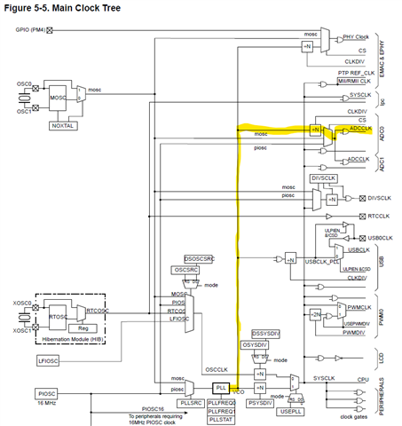
I am using a precision 3V reference, and running the ADC clock at 15MHz.

Enabling hardware oversampling or increasing the Sample Hold period seems to make very little difference.

Below is the capture of default sample settings with 15MHz sample clock and no hardware over sample in blue, followed by sample of same waveform with 32 hardware samples in Orange.

If I connect an external arduino processor to the same voltage, I get a clean waveform, see the blue waveform below.

I added some code to allow me to specify the ADC clock and calculate an appropriate divisor from my system clock of 60MHZ

ADCdivisor = ui32SysClock / ADC_CLK_SPEED;
ADCrate    = ADC_CLOCK_RATE_FULL;
ADCclock   = ui32SysClock / ADCdivisor;
if (ADCdivisor > 64)
{
	ADCrate    = ADC_CLOCK_RATE_HALF;
	ADCdivisor = ui32SysClock / ADC_CLK_SPEED / 2;
	ADCclock   = ui32SysClock / ADCdivisor / 2;
	if (ADCdivisor > 64)
	{
		ADCrate    = ADC_CLOCK_RATE_FOURTH;
		ADCdivisor = ui32SysClock / ADC_CLK_SPEED / 4;
		ADCclock   = ui32SysClock / ADCdivisor / 4;
		if (ADCdivisor > 64)
		{
			ADCrate    = ADC_CLOCK_RATE_EIGHTH;
			ADCdivisor = ui32SysClock / ADC_CLK_SPEED / 8;
			if (ADCdivisor > 64)
			{
				ADCdivisor = 64;
			}
			ADCclock   = ui32SysClock / ADCdivisor / 8;
		}
	}
}
else if (ADCdivisor == 0)
{
	ADCdivisor = 1;	
	ADCclock   = ui32SysClock;
}
rprintf("Sysclock %d Divisor %d ADC Clock %d\r\n", ui32SysClock, ADCdivisor,  ADCclock);
// ADC Clock can only be set on 
ADCClockConfigSet(ADC0_BASE, ADC_CLOCK_SRC_PLL | ADCrate,  ADCdivisor);

ADC Initialisation is

// Initialisation
ADCClockConfigSet(ADC0_BASE, ADC_CLOCK_SRC_PLL | ADCrate, ADCdivisor);
ADCHardwareOversampleConfigure(ADC0_BASE, 32);
ADCSequenceDisable(ADC0_BASE, 1);
ADCSequenceConfigure(ADC0_BASE, 1, ADC_TRIGGER_PROCESSOR, 0);
ADCSequenceStepConfigure(ADC0_BASE, 1, 0, ADC_CTL_CH13 | ADC_CTL_IE | ADC_CTL_END); // Battery Volts
ADCSequenceEnable(ADC0_BASE, 1); //Enable the ADC

Sample loop repeats the following:

ADCIntClear(ADC0_BASE, 1);          //Clear Interrupt to proceed to next data capture
ADCProcessorTrigger(ADC0_BASE, 1);  //Ask processor to trigger ADC
if (ADCIntStatus(ADC0_BASE, 1, false))
{
    ADCSequenceDataGet(ADC0_BASE, 1, RawAnalogOther);
}

I have tried just changing one parameter at a time, but don't see any improvement to the spikes.

I am applying sample and hold as follows:

ADCSequenceStepConfigure(ADC0_BASE, 1, 0, ADC_CTL_CH13 | ADC_CTL_SHOLD_16);
And adjusting hardware average as follows:
ADCHardwareOversampleConfigure(ADC0_BASE, 32);
But oversampling of 0 and 64 give same noisy output, and sample hold of 0 gives same output as sample hold 256.
Even slower sampling clock gives same level of spikes.

Hardware Oversample 0...64 gives little difference

ADC_CTL_SHOLD 2...256 makes very little difference.

Clock speed from 1MHz to 10MHz makes very little difference.

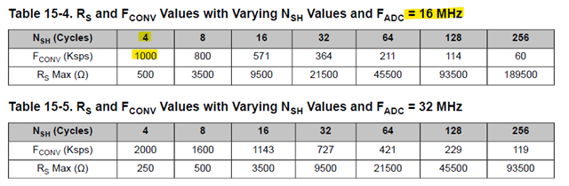
Interesting thing is that when I set 15MHz or above for the clock, my voltage output drops from 910 to 524, which seems to indicate the sample hold time is not long enough.

However, the voltage stays at this half level for sample hold time of 4 clocks or sample hold time of 256 clocks, no matter what sample hold time I use, the voltage remains at half level.

Change clock down to 10MHz and voltage is correct even with sample hold time of 4 clocks.

It looks like sample hold is not applied.

Any suggestion how I can improve the output?

  • Hi,

      I think you miss specifying which Sample Sequencer to use. There are four Sample Sequencers to choose from. Please refer to the datasheet for detail. 

    Let's say you want to use Sample Sequencer 3 to sample your analog input on AIN0. You would call ADCSequenceStepConfigure as follows. Please refer the full example source code at C:\ti\TivaWare_C_Series-2.2.0.295\examples\peripherals\adc\single_ended.c

    ADCSequenceStepConfigure(ADC0_BASE, 3, 0, ADC_CTL_CH0 | ADC_CTL_IE |
    ADC_CTL_END);

    Refer to the Peripheral Driver User's Guide for detail. 

  • I missed the line of code that does this. I am reading analog channel 13 using sequencer 1.

  • Hi,

      Have you added the call for ADCSequenceStepConfigure() and what is the result? I'm not clear why you are rejecting my answer. 

  • Hello Charles

    Sorry for the confusion. I accidently left one line out of my original code.

    I have added that into the original question, thanks for letting me know I had missed it out.

    The reason I rejected the answer is that without that line the ADC wouldn't have sampled at all.  It was a cut and paste issue on my behalf that it wasn't in the question. I am trying to understand why the output is so noisy and even if I add in the hardware averaging or increase the sample and hold period, the captured waveform looks noisy, but the same voltage measured from Arduino has much less Jitter using same input circuit.

    I want to be 100% certain that I am correctly applying the filters.

  • The reason I rejected the answer is that without that line the ADC wouldn't have sampled at all.

    That is correct. Without calling ADCSequenceStepConfigure, you have not fully configured the ADC yet. 

    I am trying to understand why the output is so noisy and even if I add in the hardware averaging or increase the sample and hold period, the captured waveform looks noisy,

    Are you saying after calling ADCSequenceStepConfigure, you still get noisy data? I'm still not clear with your statement here. If you have not called ADCSequenceStepConfigure then there is no point investigating why the ADC is capturing incorrect data. The ADC does not even know which sample sequencer to use and which ADC channel to sample data. If you have called ADCSequenceStepConfigure and still get noisy/incorrect data then we can investigate.

    I will suggest you:

      -  try out the example code and confirm if you can get correct data. This will verify the software.

      - run your own code on a Launchpad. This will verify the hardware.


  • I don't have problems getting atod values at the default example settings.  It is the things like sample hold that don't seem to work. For example the default uses piosc which is 16MHz and gives sensible value, but if i scale PLL to 16 M using the divider value, the Analog sample drops from 904 to 540 and changing the sample hold period does nothing. I am hoping someone with more experience in these things can tell me why this is the case.

  • Hi,

      There a few comments and questions I here.

      1. First of all, when you specify PLL as the clock source for ADC, it is NOT the ui32SysClock that is fed to the ADC to produce the ADDCLK after the divider. It is rather the PLL VCO that is fed to the ADC to produce the ADCCLK after a divider. The PLL VCO output depends on how you configure the System Clock. If you use the TivaWare to configure the System Clock for 120Mhz then the PLL VCO will be 240Mhz. In another word it is a fixed 240Mhz that is fed to the ADC no matter what the System Clock is. Even if you make the System Clock equal to 16Mhz, the VCO output is still 240Mhz going to the ADC. Refer to the datasheet and the Clock Tree Diagram.

    Divided PLL VCO. The PLL VCO frequency can be configured to generate up to a 32-MHz clock
    for a conversion rate of 2 Msps. The CS field in the ADCCC register must be programmed to
    0x0 to select the PLL VCO and the CLKDIV field is used to set the appropriate clock divisor for
    the desired frequency.

    ■ 16 MHz PIOSC. Using the PIOSC provides a conversion rate near 1 Msps. To use the PIOSC
    to clock the ADC, first power up the PLL and then enable the PIOSC in the CS bit field in the
    ADCCC register, then disable the PLL.
    ■ MOSC. The MOSC clock source must be 16 MHz for a 1 Msps conversion rate and 32 MHz for
    a 2 Msps conversion rate.

      2. If you are using the latest TivaWare SDK and any examples would have the below API call to configure the System Clock. As you can see the VCO is 240Mhz. 

    ui32SysClock = SysCtlClockFreqSet((SYSCTL_XTAL_25MHZ |
    SYSCTL_OSC_MAIN |
    SYSCTL_USE_PLL |
    SYSCTL_CFG_VCO_240), 120000000);

      3. The ADCClockConfigSet API does NOT alter the sample and hold time. Your statement ADCClockConfigSet(ADC0_BASE, ADC_CLOCK_SRC_PLL | ADCrate,  ADCdivisor) is used to configure the ADC source clock. As I mentioned the ADC_CLOCK_SRC_PLL is equal to 240MHz no matter what ui32SysClock is returned with. The ADCrate is used to control how often samples are provided back to the application. The ADCdivisor divides the PLL VCO to define the ADCCLK frequency and both of which have nothing to do with the sample and hold time. 

      4. The Sample and Hold time are automatically programmed when ADCSequenceStepConfigure is called. You can look at the source code of ADCSequenceStepConfigure  API.  There isn't really a need to manually change the sample/hold by user.

      5. I think your issue has more to do with the misunderstanding of the PLL VCO (240Mhz) than the sample and hold. As you can see from the below table, to achieve a 1Msps, you would need 4  ADCCLK cycles running at 16Mhz for sample/hold.  If you were to call something like ADCClockConfigSet(ADC0_BASE, ADC_CLOCK_SRC_PLL | ADCrate, 1), you are actually programming the ADCCLK for 240Mhz as in 240 divide by 1. This is of course incorrect.  ADC can't run with a 240Mhz clock. To achieve 16Mhz of ADCCLK using PLL VCO you would need to call something like ADCClockConfigSet(ADC0_BASE, ADC_CLOCK_SRC_PLL | ADCrate, 15).

  • Thanks for the response. This has led me to the correct answer.  I investigated further on the PLL VCO as you suggested and found the TM4C129 

    SysCtlClockFreqSet function is passed a parameter to set the PLL VCO frequency.  This has options of 
    SYSCTL_CFG_VCO_320 or SYSCTL_CFG_VCO_480 which set a frequency of 320MHz or 480MHz.
    My setting of the sample and hold period in the individual sample steps was having no impact because 4 clocks was sufficient, and hence making it longer had no improvement on the voltage measured.