Part Number: TMDSCNCD263P
Other Parts Discussed in Thread: TCA6424, TCA6424A
Tool/software:
Hello,
I'm trying to follow your examples for OSPI flash usage.
<Question 1>
I appreciate there are hardware differences between E2 and A of TMDSCNCD263P which mean the OSPI reset pin is toggled by different peripherals in function board_flash_reset(). However, there's still a subtle difference between the pin logic levels for the same OSPI flash IC.
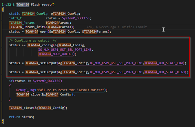
Rev E2 (in TCA6424_Flash_reset())
status = TCA6424_setOutput(&gTCA6424_Config,IO_MUX_OSPI_RST_SEL_PORT_LINE,TCA6424_OUT_STATE_LOW);
status = TCA6424_setOutput(&gTCA6424_Config,IO_MUX_OSPI_RST_SEL_PORT_LINE,TCA6424_OUT_STATE_HIGH);
Rev A:
OSPI_setResetPinStatus(oHandle, PIN_STATE_HIGH);
OSPI_setResetPinStatus(oHandle, PIN_STATE_LOW);
For E2 and A, why are the logic level sequences reversed?
<Question 2>
All the TI examples call flashFixUpOspiBoot(). If my application is just reading from OSPI flash do I need to call flashFixUpOspiBoot() at all? Put another way, when do I need to call flashFixUpOspiBoot()?