This thread has been locked.

If you have a related question, please click the "Ask a related question" button in the top right corner. The newly created question will be automatically linked to this question.

AM263P4: ADC digital value to analog value

Part Number: AM263P4

Tool/software:

Hello,

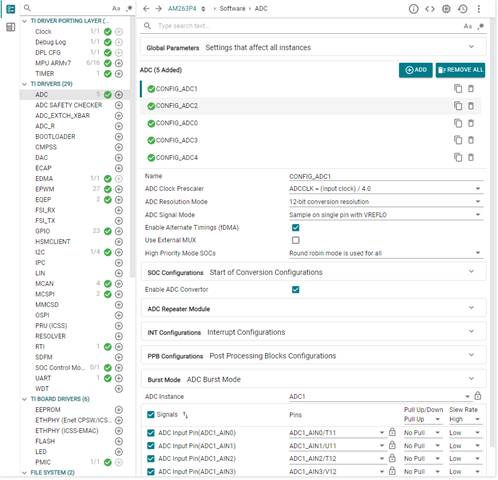
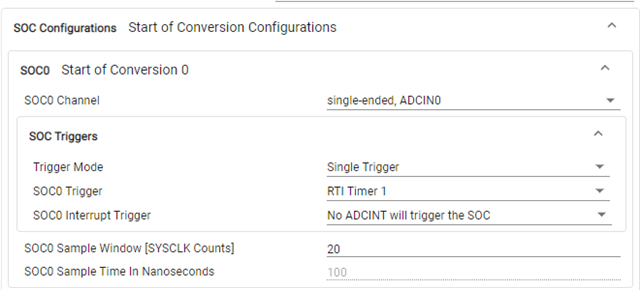
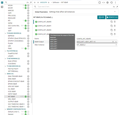
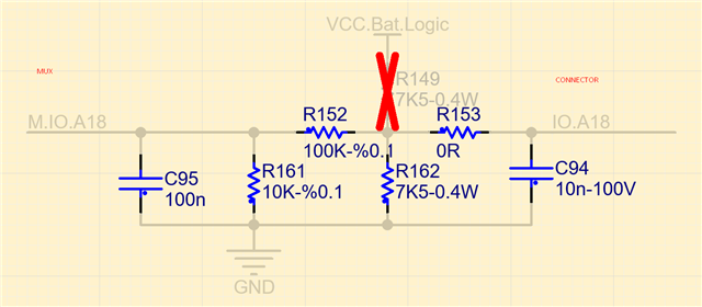
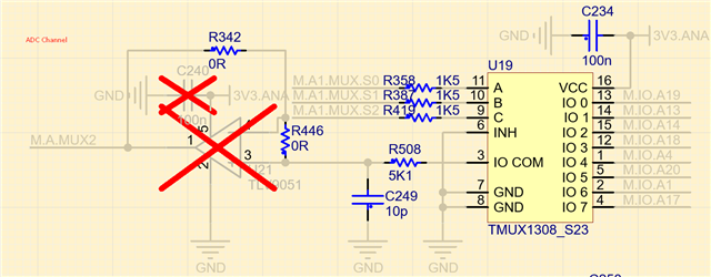
I have a custom board of AM263P4 and I am working on I/O modules. I have more than 40 ADC channel in my board and they are reading one-by-one with mux. I used the "ADC SOC RTI" example in SDK but I changed a few thing to adapt multi channel ADC.

My question is: 

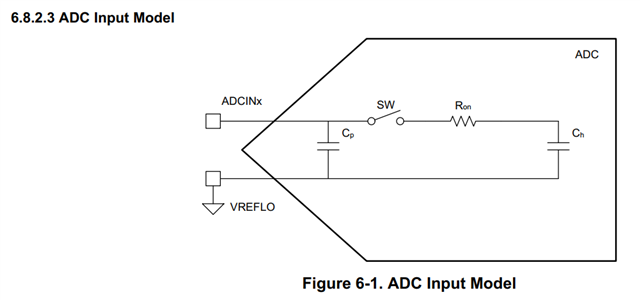
I am reading ADC digital values from ADC_RESULTS_ADCRESULT0 register with "ADC_readResult" function. How should I calculate analog voltage from digital value?

I found this equation in reference  manual but this is not giving me correct analog value.
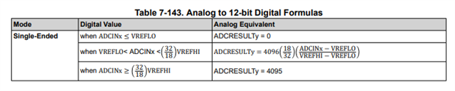
Thank you for help.
Best Regards,
BK


In my board, 

VREFHI = 1.8V

VREFLO = 0V

Some test results:

Voltage Value Raw Value(Register)
2697mV 3176
396mV 628
2121mV 2528
312mV 535
  • Hi Basri,

    Can you please share your full setting on the ADC module and which ADC you are using. Also, please share a schematic on how your external test signal is connected to the device. Thanks.

    Han

  • Hi Han,

    I can not share my syscg file because this website is blocking that. Therefore, you can find my configuration inside of the pictures. I will all of the pins inside of configuration. Values that I shared belong to ADC4-AIN1 and ADC1-AIN2.

    SOC configuration is same for AIN. I am trigering all channels with RTI.
    Other configurations are same as SDK example.


    Scheamtic:

  • Hi Basri,

    Does the M.A.MUX2 signal doing directly to MCU ball? The C249 is only 10 pF and is too small for input bucket capacitor.

    Han

  • Hi Han,

    After output of mux, there is just C249. “M.A.Mux2” is connected to MCU-ADC pin.

    I realized after sharing the schematic with you that TL9051 did not use.

    Is the bucket capacitor problem in my case? Do you have any recomendation? I can try on my board.

    Basri

  • Hi Basri,

    Refer to the input model for ADC, sample capacitor Ch is 8 pF. Recommendation for input bucket capacitor is > 20x larger than Ch and low impedance input. Since you have a 5.1 kOhm filter resistor, it is better to have a larger input capacitor.

    Please try to use a larger input cap. If you don't want to make HW change initially, you can try to change sample window to a much larger value, and see if the result is better (closer to expected value).

    Han

  • Hi Han,

    I made a few test on my board and I figure out that resistor values on board are not same as in variant file(100K-9.53K). Therefore, I was making the calculation with wrong values. 

    On the other hand, I tried different combination for ADC input but I did not see any difference for 12V input. I have to test with different voltage ranges. If I test something like that, I will share my results under this section.

    I tried the combinations below:
    5K1 - 10pF
    0R - 10pF
    5K1 - 330pF

    I am not sure about using a larger cap because I am using  a switch(Mux) before ADC inputs. How should I test this case?