Part Number: LP-MSPM0G3507
Other Parts Discussed in Thread: MSPM0G3507,
Tool/software:
Hi,
I’m currently working on implementing firmware upgrades via UART1 and have chosen to use the plug-in interface. To begin, I tried running the example project bsl_uart_flash_interface_LP_MSPM0G3507_nortos_ticlang using CCS. However, the example doesn’t seem to work, even though I haven’t made any modifications to the code.
Here’s the process I followed:
1. Performed a factory reset
2. Launched the debug session with the flash setting set to “Erase MAIN and NONMAIN memory”
3. Terminated the debug session and power-cycled the device
4. Used a PC as the host to send commands to the device
-> Received no response from the device
For reference, the same host commands work correctly when using the default ROM-BSL.
Since both address 0x00 and 0x04 are blank, the device should automatically enter BSL mode, correct?
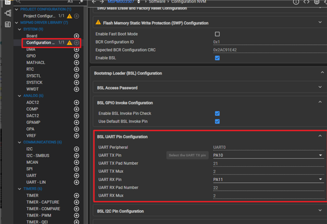
Additionally, below are the settings I’m using to configure UART1 (PA17, PA18). Could you please let me know if there’s anything I should modify?
#define BSL_GPIO_UART_TX_PIN (38U) //IOMUX_PINCM39
#define BSL_GPIO_UART_RX_PIN (39U)
#define BSL_GPIO_UART_TX (2U) //IOMUX_PINCM39_PF_UART1_TX
#define BSL_GPIO_UART_RX (2U)
/* Definitions for UART */
#define BSL_UART (UART1)
#define BSL_UART_INTERRUPT_NUM (UART1_INT_IRQn)
#define BSL_UART_CLOCK_SOURCE (DL_UART_MAIN_CLOCK_BUSCLK)
#define BSL_UART_DEFAULT_BAUD ((uint32_t) 9600U)
#define BSL_UART_CLOCK ((uint32_t) 32000000U)