MSPM0G3506-Q1: The sleep mode current issue

Part Number: MSPM0G3506-Q1

Tool/software:

Hi, 

We use the MSPM0G3506-Q1 in out new project, and we have below issue for our design:

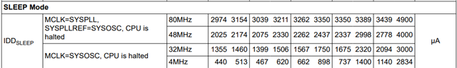
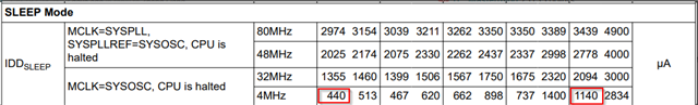
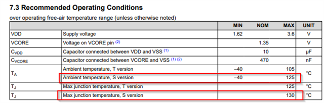
1. We have tested that there is 1.67ma in the 125 degree sleep state. What should we pay attention to in terms of power saving?

2. The CPU starts at 25 degrees Celsius, and as the temperature rises and the current increases, it never stops rising. At 25 degrees Celsius, the Sleep current is 0.67mA,

     and when it reaches 125 degrees Celsius, the current is 1.67mA; it rising to 150 degrees, the CPUSleep current reached 3.2mA

3. The current is abnormal within the normal temperature range. Do you want to know where we haven't dealt with it properly?

  • Hi Liang,

    So, which low power mode are you using?

    Some guidance in low power please refer to below application note:Low Power Optimization Guide

    B.R.

    Sal

  • Hi Sal,

    So, which low power mode are you using?

    We use the Sleep mode 1.

  • Hi Liang,

    [Update with some description fixed]

    So in sleep mode, the typical power consumption is below:

    You have tested that the IDD is 670uA in room temperature (25C). As you set it in SLEEP1 mode, so it should be smaller than 467uA.

    I assume you used SYSOSC=4MHz, and enable few peripheral worked in SLEEP mode. If so, I think the tested data is within expectation.

    I do not think it is much larger than my expectation, other peripheral remained enabled will also cost additional power consumption.

    - To save the power, disable the peripheral not used properly before enter low power mode, see the low power optimization guide I shared for more details.

    To have better low power performance, you can also use STOP or STANDBY mode.

    B.R.

    Sal

  • Hi Sal,

    Thanks for you kindly support.

    We also don't know why the tested power consumption increases with temperature, the 25℃ is 0.9mA, 125℃ is 1.59mA and 150℃ is 3.3mA,

    we consider that it is not complies with the description in the datasheet, can you help to explain?

    BTW, can you help to confirm with your test Department if TI test the power consumption vs temperature from 125℃ to 150℃, thanks.

  • Hi Liang,

    We also don't know why the tested power consumption increases with temperature, the 25℃ is 0.9mA, 125℃ is 1.59mA and 150℃ is 3.3mA,

    This is under expectation. When temperature increased, the power consumption increased. The test data of the data sheet is also has similar situation.

    can you help to confirm with your test Department if TI test the power consumption vs temperature from 125℃ to 150℃, thanks.

    No, we don't. Our device can not work over than 125 Ta (130Tj). 

    B.R.

    Sal

  • Hi Sal,

    Thanks for your kindly support.

    We have below technology issue for the temperature:

    1: When the CPU runs at 32MHz, the ADC sampling value is 0, the ADC uses ULPCLK, with VREF set to 2.5V, and generates an interrupt

        when sampling ends. Previously, we always performed ADC with the CPU operating at the DL_SYSCTL_SYSOSC_FREQ_4M frequency of 4MHz,

        and the sampling values were basically correct.

        However, it has been discovered that when under high load, the CPU switches to a frequency of 32MHz for DL_SYSCTL_SYSOSC_FREQ_BASE,

        and the ADC sampling value is 0. At this time, the ADC sampling interrupt will occur normally, but the read data is always/completely 0x00.

       In these two scenarios, all other settings are the same, except for the setting of the system clock through DL_SYSCTL_setSYSOSCFreq().

       Please advsie why this issue is happen?

    2. During high and low temperature testing, there is a significant difference in ADC sampling values:

        The sampling values of the same analog input vary greatly at different temperatures.
         26℃: 0x020A;
         48℃: 0x020F;
         80℃: 0x0200;
       100℃: 0x01E3;
       120℃: 0x01B9;
       130℃: 0x0199;
       140℃:0x016D;
       150℃:0x013D;
         If the temperature above 125 ℃ exceeds the standard range, let's not talk about it. However, below 125 ℃, the difference in ADC sampling values
         for the same source is far beyond our understanding.
  • Hi Liang,

       Please advsie why this issue is happen?

    Do not set ADC sampling time as 0. set a proper value on it. Normally 200-500ns should okay.

    owever, below 125 ℃, the difference in ADC sampling values
         for the same source is far beyond our understanding.

    Firstly, please set a proper sampling value. Then, please see below app note for ADC operation:https://www.ti.com/lit/an/slaaeo8/slaaeo8.pdf 

    It does has noise when ADC works, I believe there has different noise when works in different temperature. Enable the hardware average mode if not required high speed sampling, then it should looks better on the conversion result.

    Additionally, check your input waveform, sometimes it also has some drift with different temperature.

    B.R.

    Sal