AM263P4-Q1: Synchronizing resolver signal sampling with motor PWM current sampling

Part Number: AM263P4-Q1
Other Parts Discussed in Thread: TIDM-02018, SYSCONFIG

Tool/software:

Hi,

I am fairly new to the AM263P4-Q1 and working myself into an existing project.

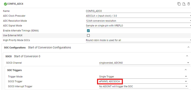
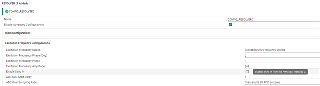
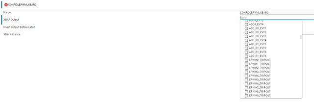
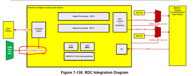
As stated in the title I want to synchronize the resolver signal sampling with the motor PWM current sampling as proposed in the technical reference manual 7.5.3.1.6 - Step 5.2:

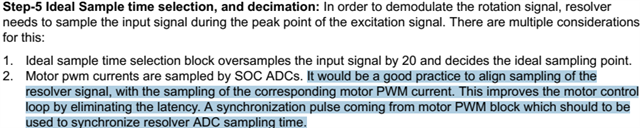
Is there any guideline how to do as proposed in the last sentence marked: "A synchronization pulse coming from motor PWM block which should to be used to synchronize resolver ADC sampling time." ?

Best regards

Norbert

  • Hi Norbert,

    This expert is currently out of office due to the holiday. Please expect a delay in response until their return next week.

    Best Regards,

    Allison

  • Hello Norbert,

    The intended method is to use the EPWM synchronization features to align the resolver ADC sampling with the motor current sampling. The general flow is: 

    • Configure your motor control EPWM module to generate a SOC say SOCA at the desired instant.

    • Map that SOCA to both the ADC channels for phase current and the ADC channels for resolver signals.

    • This ensures the resolver and current are sampled in sync with the PWM.

    Best Regards,

    Masoud

  • Hi Masoud,

    thanks a lot.

    While I can find the setting for the normal ADC in the syscfg gui:

    I can't find anything similar in the Resolver parts.

    Can you show me where to put this information?

    Best regards

    Norbert 

  • You can check the example on "C:\ti\motor_control_sdk_am263x_<version>\examples\tidm_02018_universal_motorcontrol" as reference and let me know if this resolves the issue. The marked location in your screen shot is the right place to set ADC SoC trigger.

    Best Regards,

    Masoud

  • I think the main question of Norbert is, how to enable the synchronisation of the resolver module.
    The example you mentioned Masoud is for am263x, which doesn't have the resolver module.


    if iam correct, you can enable the sync in the excitation freq menue of the resolver. The input for the sync is PWMxbar2

    there the PWMx_TRIPOUT can be choosen. But where can i configure this?

    Best regards,

    Marcel

  • Hello Norbert / Marcel,

    TIDM-02018 is the software based on AM26x that demonstrates how the ADC syncs with PWM. Once it's out, the AM263Px based traction inverter will serve as the perfect reference for showcasing the ADC-PWM-Resolver sync.

    Regarding PWM-Resolver sync, the resolver’s SYNC_IN should come from the PWM XBAR, and the cleanest source is an ePWM SYNCOUT or a well-timed SOCA pulse if you prefer. In SysConfig you can wire this up end-to-end, first enable “Sync In” at “Resolver -> Excitation Frequency Configuration” and select PWMXBAR2 as the sync source (matches the TRM note).

    Then map PWMXBAR Output 2 to EPWMx SYNCOUT (e.g., EPWM0 SYNCOUT).

    Now, configure your ePWM to assert SYNCOUT at the sampling instant you want (e.g., CTR=ZERO or CTR=PRD, depending on where you sample currents).

    If you prefer using SOCA for ADC current sampling, you can still keep SYNCOUT aligned to that instant so resolver sampling lands at the same phase of the PWM.

    Best Regards,

    Masoud

  • Hey Masoud,

    thats what we are looking for, we try that out. Maybe you change the note in systemconfig:

    because we tried using EPWM XBAR (like the hints says) instead of EPWM SYNCOUT XBAR.

    For motorcontrol it's also important to know the delay between PWM Output and Resolver measurement. Now we have synced Resolver excitation frequency to the PWM. Measurement is done at the peak of excitation frequency and frequency is 20kHz. So i asume the delay is 12.5µs (time till peak of frequency) + Resolver ADC measurement time?

    Best regards

    Marcel

  • Hello Marcel,

    Great point, thanks for calling it out. The earlier “EPWM XBAR” hint is misleading in this context; we’ll flag that note.

    When SYNC_IN = 0 phase, the resolver excitation sine starts at zero-crossing; the resolver block samples the SIN/COS at the peak of the excitation. So the nominal delay from the SYNC event to the sampling instant is (((90 + ex_offset) / 360) * Texcitation). With zero offset and excitation frequency of 20KHz (50 us), that’s 12.5 us plus your S/H and any external RC/group delay. In other words, your 12.5 µs + ADC time intuition is on the mark. The exact digital pipeline latency doesn’t change the phase alignment, only when the result appears.

    To measure real skew on hardware, route SYNCOUT to a spare pin (via XBAR) and toggle a GPIO at the resolver-ADC ISR entry, then scope the delta.

    Best Regards,

    Masoud

  • Hey Masoud,

    how do i activate an resolver-ADC ISR?
    In sysconfig in resolver tab, there are only interrupts for errors. And i thought the ADC_R tab is only used if i use this as normal ADCs and not for the resolver module?

    Best regards,

    Marcel

  • The Resolver SysConfig node only exposes status/error IRQs (loss-of-tracking, overflow, etc.). Your sample-by-sample ISR must come from the ADC that’s sampling SIN/COS, that’s exactly what the ADC_R instance is for. Even when you use the Resolver module, you still enable the “conversion-complete” interrupt on ADC_R, not on Resolver.

    Best Regards,

    Masoud

  • Okay, but i have to enable the ISR manualy in my SW and can't do this in systemconfig? 
    Because i already used the resolver wrapper and should't use the ADC_R wrapper, like mentioned in this case: https://e2e.ti.com/support/microcontrollers/arm-based-microcontrollers-group/arm-based-microcontrollers/f/arm-based-microcontrollers-forum/1401698/am263p4-q1-adc_r0-and-adc_r1-soc-signal/5367901?tisearch=e2e-sitesearch&keymatch=am263p%2520adc_r#

    Best Regards,

    Marcel

  • Hello Marcel,

    The “data-ready / conversion-complete” interrupt is not auto-wired by the resolver node. If you want an ISR that runs each sample/decimation hit, you must add it yourself. You do not need to switch to the ADC_R wrapper for the data path, you can keep using the resolver wrapper and simply create a Hwi for either ADC_Rx INT (EOC) or the resolver “result ready”.

    As the topic of thread changed from ADC and ePWM, I'll ask team to assign the thread to a resolver expert from here.

    Best Regards,

    Masoud

  • So ADC_Rx INT (EOC) would be before RCD calculations?
    I can't find any resolver "result ready" interrupt. Can you tell me in detail how to enable it?

    Best Regards,

    Marcel

  • + how to enable and route the interrupt without using systemconfig 

  • Hi Marcel, I have assigned this ticket to someone who can help with resolver question.

    Best regards,

    Ryan Ma

  • Hi Marcel, 

    There is no currently available Interrupt that can suggest the SW, RDC results are available. the ADC_R is a Digital Wrapper on the ADC. the ADC are exclusively used either by ADC_R digital wrapper or the Resolver's Sequencer. so please do not get confused between the ADC_Rx INT (EOC) with the RDC's ADC Sampling or the RDC result ready. 

    To be clear, in AM263Px Resolver IP doesn't have any result ready signal to the CPU. there are only Err Interrupts like Masoud Mentioned earlier in this thread.

    Thanks,

    Madhava