Part Number: TMS570LC4357-SEP
Other Parts Discussed in Thread: LP-XDS110
Tool/software:
I am working with a custom board that uses the TMS570LC4357-SEP controller, and I plan to program it using the LP-XDS110 kit. My custom board will have seperate power, so I don't need to supply it with the LP-XDS110 kit. I have two questions:
-
Firmware on LP-XDS110
-
Do I need to upload any firmware to the LP-XDS110 before I can use it to program my custom board?
-
If yes, what firmware is required, and how do I upload it?
-
-
Interfacing nTRST
-
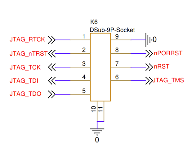
My custom board has the following connections (JTAG signals).
-
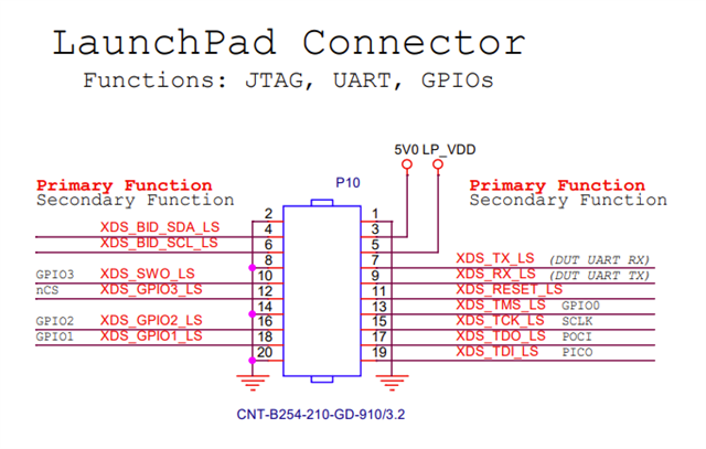
From what I understand, the LP-XDS110 does not provide an nTRST output. How should I interface the LP-XDS110 with my custom board? I do not want to keep nTRST pulled HIGH by default on my card.
-