Tool/software:
Hi experts,
We have encountered strange temperature readings from one of the three internal temperature sensors.
The device was placed in a temperature chamber and cooled down to -40°C.
At startup, the software:
- reads the temperature calibration values from the OTP and calcualtes the slopes and offsets (lines 1-18), as described in the Application Note SPNA216–January 2016
- configures and tests the internal ADC and enables the internal temperature sensors in the IOMM
- reads ADC1[31](=ITMP1), ADC2[30](=ITMP3) and ADC2[31](=ITMP2)
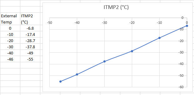
Now the sensor 2 readout (line 25) is way off from the expected temperature of -40°C with an actual temperature value of -49°C.
This value is calculated with the correction values already applied.
Our assumption was, that the sensors readings will have an accuracy of about +/-2,5K across the full temperature range
==> Question (a): Is this assumption correct for all sensors, even with the calibration correction applied?
Or is this only valid after some sort of "2oo3 voting" as suggested in the manual?
As there are calibration values for 233K (-40°C) (lines 3,9,15) we also dumped the raw value of the ADC readings (lines 20-22):
[2/3]233K = 1531/0x5FB raw <=> ITMP1raw = 0x000005FE ==> diff: +3
[2/3]233K = 1555/0x613 raw <=> ITMP2raw = 0x000005DF ==> diff: -52
[2/3]233K = 1538/0x602 raw <=> ITMP3raw = 0x0000060C ==> diff: +10
Sensor 1 and 3 readouts are slightly higher than their calibration values, which makes sense, because of the self-heating of the device.
Sensor 2, on the other hand, is 52 digits below the calibration value, which looks kind of odd.
==> Question (b): How can the raw temperature reading be way below the calibration values?
Currently we are experiencing this issue with only one device, but we want to make sure, that this is not a general misunderstanding or error of any sort.
We tested 5 more devices that are much closer to the calibration values, but as the sensors are fully integrated on the chip it is difficult to imagine a faulty chip being the cause.
There are other signals connected to the internal ADCs that seem to have a valid readout.
Also the internal ADC test procedure runs without indicating any issues.
So, as far as we can tell, the A/D conversion itself appears to be functioning correctly.
- ADC base clock is 1/93,3ns (VCLK=75MHz and Prescaler set to 6(+1))
- Sampling Cycles = 255 (+2 => 257 * 93,3ns = 24us)
- Discharge Cycles = 255 (*93,3ns = 23,8us)
[2025-08-15 09:58:22.450] [001] ===== [0] =============================================
[2025-08-15 09:58:22.450] [002] [1/3]303K = 1934/0x78E raw
[2025-08-15 09:58:22.450] [003] [2/3]233K = 1531/0x5FB raw
[2025-08-15 09:58:22.450] [004] [3/3]398K = 2486/0x9B6 raw
[2025-08-15 09:58:22.450] [005] slope =0.173
[2025-08-15 09:58:22.450] [006] offset=180.701
[2025-08-15 09:58:22.450] [007] ===== [1] =============================================
[2025-08-15 09:58:22.450] [008] [1/3]303K = 1965/0x7AD raw
[2025-08-15 09:58:22.450] [009] [2/3]233K = 1555/0x613 raw
[2025-08-15 09:58:22.450] [010] [3/3]398K = 2496/0x9C0 raw
[2025-08-15 09:58:22.450] [011] slope =0.176
[2025-08-15 09:58:22.450] [012] offset=231.065
[2025-08-15 09:58:22.450] [013] ===== [2] =============================================
[2025-08-15 09:58:22.450] [014] [1/3]303K = 1945/0x799 raw
[2025-08-15 09:58:22.450] [015] [2/3]233K = 1538/0x602 raw
[2025-08-15 09:58:22.450] [016] [3/3]398K = 2492/0x9BC raw
[2025-08-15 09:58:22.450] [017] slope =0.173
[2025-08-15 09:58:22.450] [018] offset=191.383
[2025-08-15 09:58:22.450] [019]
[2025-08-15 09:58:22.450] [020] ITMP1raw = 0x000005FE
[2025-08-15 09:58:22.450] [021] ITMP2raw = 0x000005DF
[2025-08-15 09:58:22.450] [022] ITMP3raw = 0x0000060C
[2025-08-15 09:58:22.450] [023]
[2025-08-15 09:58:22.450] [024] ITMP1 = 234.542 K (==> -38,608°C)
[2025-08-15 09:58:22.450] [025] ITMP2 = 224.029 K (==> -49,121°C)
[2025-08-15 09:58:22.450] [026] ITMP3 = 235.472 K (==> -37,678°C)
[2025-08-15 09:58:22.450] [027] DIF13 =   0.930 K
[2025-08-15 09:58:22.450] [028] DIF23 =  11.443 K
Thank you and best regards,
Max


