


Part Number: LP-MSPM0G3507
Other Parts Discussed in Thread: MSPM0G3507
Tool/software:
Hello,
I wanted to start off by stating that I am using DriverLib to attempt to get the functionality listed below.
I am attempting to write a driver which will allow my program to send and receive data over the UART peripheral. The amount of data I need to transmit and receive will vary (of course). Given that the amount of data I need to send exceeds the FIFO size (4-bytes) so polling won't work and I must use DMA. To understand how the interaction between the two peripherals work I have been referencing the following example projects:
- uart_rx_multibyte_fifo_dma_interrupts_LP_MSPM0G3507_nortos_gcc
- uart_tx_console_multibyte_repeated_fifo_dma
The DMA and UART were not configured differently than how they come with the example project.
Let's start with the RX
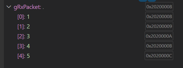
My goal is to create a read function that can be called by my application to read data from an IC. The example project shows how to setup the peripheral when only executing 1 read. When testing out the code, this seems to work fine. But when I move this into a function and call it within the infinite loop I begin to get weird behavior. The data is not being received correctly. For example, when I send the following characters ('12345') to the program, using the example project, I get:
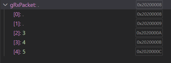
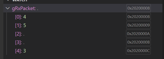
But, when I move the logic into a function and send the same characters, I get the following two instances. As you can see, the behavior is not as expected.
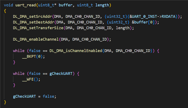
Below is a snip-it of the function.
So my question(s) are:
- What is the correct sequence of events I need to do to be able to read data through UART without any issues?
- Why is my data not appearing sequentially?
- If I am expecting 5 bytes in my DMA and my rx trigger is set to "RX FIFO contains >= 1 entry", what is the sequence of events between the DMA and UART.
- I understand that the DMA will trigger an interrupt when it has received it's full 5-bytes.
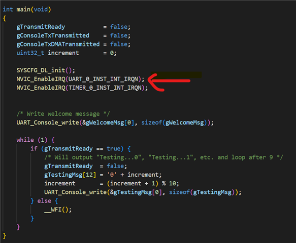
Now with TX
The example project makes sense since it already moves the UART write functionality into a function that can be called periodically by the application. I assume I can carry over this into my program without any issues. BUT the thing that I am unsure about is how this example code will behave when I introduce the ability to read data. Let me explain.
In the example program, the UART interrupts are enabled BEFORE configuring the DMA (src, dest, size, etc) and it is kept enabled throughout the lifetime of the program. Whereas in the read example the interrupts are enabled AFTER configuring the DMA.
TX example program
RX example program
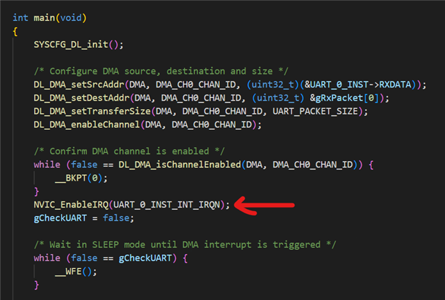
I'm not sure when the UART interrupts need to be enabled and if it is enabled before/after (depending on write or read), I am going to run into any issues.
So my question(s) are:
- What is the correct sequence of events when a write AND a read need to happen in the same application?
Maybe my confusion between the logic with the write and read is coming from not fully understanding how the DMA interacts with the UART when it comes to generating interrupts, firing with the triggers, and the sequence of events within this behavior. I don't want to make this post any longer than it is now trying to convey my current understanding of it, but I can if need be. Sorry for a long post. I am trying to fully understand how the UART peripheral works with DMA to prevent any issues that can occur later on.
Thank you in advance for your much needed help and hopefully I conveyed myself well enough for you to understand.
Thanks,
Adan Pantoja
