This thread has been locked.

If you have a related question, please click the "Ask a related question" button in the top right corner. The newly created question will be automatically linked to this question.

MSPM0G3507-Q1: Unstable Clock -->> PLL Problems?

Part Number: MSPM0G3507-Q1


Tool/software:

Hello,

we have integrated the MSPM0G3507-Q1 for a custom design. We added a 24 MHz external Crystal (load capacitance 8 pF --> we use 12 pF capacitance on XTAL). We verified the crystal with the scope and its in the specified tolerance range.

We got some samples and flashed these with our SW. Our SW creates a simple PWM Timer with a clock of 5 MHz. If the PCB gets hotter then the clock gets more instable (PLL active), the timer clock fluctuates around some khz and thats not in the tolerance range.

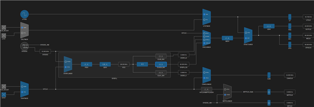
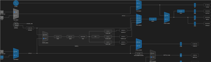
Originally Clock tree configuration

I made some tests and I used a simple example GPIO_toggle_output and modfified this. I just modified the Clock tree and added a pwm timer with 5 MHz, no gpio pins are toggling.

The aim was to identifiy the origin of the instability, I made 4 tries:

First try:

Only usage of internal Clock SOSC with this Clock tree configuration

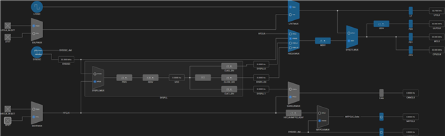
--> 4 MHz clock output stable

Second try:

Only usage of internal Clock SOSC with PLL active

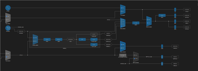
-->4 MHz clock ist not stable when PLL is active--> It's probably due to the PLL

Third try:

External 24 MHz Crystal without PLL--> 4MHz clock output stable

Fourth Try:

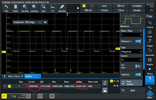
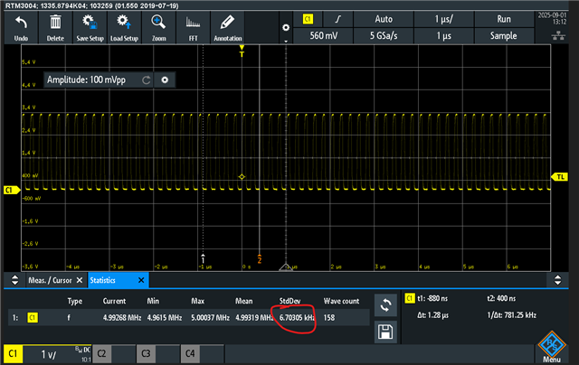
External 24 MHz Crystal with PLL (original clock tree)--> 5MHz clock outptut not stable

Picture from scope (std deviation >6 kHz increases until 30 kHz)

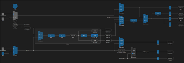
If i reduce enlarge the clk2x_Div from 6 to 8 --> CPU_CLK has 

60 MHz instead of 80 MHz --> output clock of timer (5 MHz) is also stable!

scope picture (std deviation <200 Hz)

So it seems that there is a problem with PLL configuration. 

In SYSCTL "Enable Check for Clock Stabilization" is always on. We use CCS 20.0 but it doesn't matter which version we use. We have also samples where we have no problems with the 80 MHz output PLL configuration.

We are not sure if some of our MCUs has a temperature problem, a soldering problem is not visible. Sometimes we change the IC and then it works with the original configuration. Is there any known problem with PLL config or clock config or timer config, which can cause a unstable clock with a temperature increase (any prescaling settings or something else)?

  • I check datasheet SYSPLL section, there is no temperature related spec.

    Could you please share me the amount of PCB that you have test?

    We got some samples and flashed these with our SW. Our SW creates a simple PWM Timer with a clock of 5 MHz. If the PCB gets hotter then the clock gets more instable (PLL active), the timer clock fluctuates around some khz and thats not in the tolerance range.

    What's the temperature you have test? Just 50C or increase to 80C or 120C?

    It seems there are 0.1% error.

    ----------------------------------------

    Could you please help me test these condition?

    Since HFXT 24MHz can not use SYSPLL0 to generate 80MHz for CPU, we can try to use SYSOSC.

    1. SYSOSC 32MHz -> PDIV /4 -> QDIV *20 -> VCO 160MHz -> CLK0_DIV /2 -> SYSPLL0 80MHz -> CPU

    2. SYSOSC 32MHz -> PDIV /4 -> QDIV *20 -> VCO 160MHz -> CLK0_DIV /4 -> SYSPLL0 40MHz -> CPU

    1 and 2 is to check whether this is related to SYSPLL0 and SYSPLL2X, or it's related to 80MHz or not 80MHz.

    Want to check your use case, do you need CPU 80MHz?

  • We have tested approximately 20 PCBs with the same software, and in about 30% of them, the generated timer clock is unstable. We would rule out a manufacturing problem for the time being.

    I made your suggested tests and i did not saw a difference between SYSPLL0 an SYSPLL2X. If I reduce the CPU Clock to 40 MHz the deviation is a bit better.

    I have created a very simple piece of software that only initialises a timer and generates a 2.66 MHz clock. I am using the external crystal, and measured the frequency of it which appears to be very stable.
    The behaviour is not always the same. Sometimes the clock frequency is very unstable, up to 10 kHz deviation, and sometimes it is a few hundred hertz. It seems to me that sometimes the initialisation of the PLL does not work, which causes the deviation. Is there any SDK version or CCS version where the driver library has changed and such behaviour can occur? I use MSPM SDK Version 2.5.1 and CCS 20.0 and I also used it with SDK version 2.3.7. I had the same problem.

  • I use MSPM SDK Version 2.5.1 and CCS 20.0 and I also used it with SDK version 2.3.7

    This is the latest SDK version, Version: 2.05.01.00

    It seems to me that sometimes the initialisation of the PLL does not work, which causes the deviation.

    If you are concern about SYSPLL setup initialization issue, there are another E2E thread that talked about this, put it here as reference. MSPM0G3507: TRM error in SYSPLL setup example [SLAU846B Sec 2.3.1.3.1] 

    scope picture (std deviation <200 Hz)

    Re-check your scope result, since std is vey large, do you have jitter test result from oscilloscope?

    Trigger at rising edge of PWM and capture the falling edge or next rising edge, enable the image retention function.

    To see how large the jitter is.

    There is jitter spec in datasheet: 7.9.3 System Phase Lock Loop (SYSPLL)

  • .

    The deviation is very high and out of spec:

    This is the clock tree with 80 MHz MCLK:

    These are the timer settings:

    This is the very unstable timer output:

    Sometimes it is still higher or lower: 

    If you capture some minutes there are also time periods where the deviation is very low some 100 hertz.

    If I only set the CLK2X_DIV from 6 to 8 MCLK has 60 MHZ and I have no problems, see following picture 

    Here we have no problem we have just a deviation of about 360 Hz. The frequency in this picture is lower because the timer setting are as before but the MCLK has still 60 MHz.

    If I use the external oscillator, it is still the same with lower deviation

  • If the PCB gets hotter
    What's the temperature you have test? Just 50C or increase to 80C or 120C?

    Any temperature range?

  • MCU has just 50 to maximum 70 °C

  • got it~

    Thanks for feedback.

  • I check the previous talk.

    Need to confirm more things:

    Since HFXT 24MHz can not use SYSPLL0 to generate 80MHz for CPU, we can try to use SYSOSC.

    1. SYSOSC 32MHz -> PDIV /4 -> QDIV *20 -> VCO 160MHz -> CLK0_DIV /2 -> SYSPLL0 80MHz -> CPU

    2. SYSOSC 32MHz -> PDIV /4 -> QDIV *20 -> VCO 160MHz -> CLK0_DIV /4 -> SYSPLL0 40MHz -> CPU

    I made your suggested tests and i did not saw a difference between SYSPLL0 an SYSPLL2X. If I reduce the CPU Clock to 40 MHz the deviation is a bit better.

    Do you keep the fVCO = 160MHz in your feedback and result keeps same phenomenon?

    In order to eliminate the interference that may be caused by the Timer, please try to use ClkOut pin to directly output clock to M0's pin:

    In syscfg - Clock Tree View - Clock Output and FCC

    Please use SYSOSC as SYSPLL's clock source and keep VCO = 160MHz.

    1. Choose ULPCLK (Source from SYSPLL when CPU = 80MHz, ULPCLK will = 40MHz(Half of CPU/MCLK)) and add some EXCLKDIV like ULPCLK/10 = 4MHz output to a clokout pin.

    2. Choose SYSPLL1 as output.

    Then monitor this clockout pin's jitter.

  • Thanks, I will try this on Monday and give you feedback then

  • So if I hold VCO below 160 with external Crystal the CLK is stable. If it is above 160 the clock ist unstable. Is there a recommendation in the datasheet or somewhere else to hold VCO below 160 MHZ?

  • In datasheet you can see a limit of 400 MHz

  • Thanks for your feedback.

    Referring to the previous talk, if VCO is 160MHz, PLL is unstable. Could you please double check this test point?

    In datasheet you can see a limit of 400 MHz

    Now, datasheet limit VCO between 80 ~ 400Mhz, but still recommend customer to use a 8/16/32MHz external HFXT and set VCO to 160MHz.

  • Okay but this customer recommendation is still not written in any document? With the internal oscillator clock is stable with VCO=160 MHz. With an external crystal of 24 MHz it is not possible to reach VCO=160 Mhz with the divider settings. If we are above 160 MHz it is getting more and more unstable, below it is stable. So we are thinking about to change the crystal to 16 MHz then we can make a VCO setting to 160 MHz to reach a CANCLK of 80 or 40 MHz. This is important for us. So do you recommend to stay below 160 MHz with an external Crystal or is 160 MHz also okay? 

  • Because of never seen VCO>160MHz unstable issue in 40~70C temperature before.

    So it often works normally.

    This is important for us. So do you recommend to stay below 160 MHz with an external Crystal or is 160 MHz also okay? 
    1. SYSOSC 32MHz -> PDIV /4 -> QDIV *20 -> VCO 160MHz -> CLK0_DIV /2 -> SYSPLL0 80MHz -> CPU

    In earlier reply, I have ask the result of VCO = 160MHz, this is why I want to double confirm with you whether VCO=160MHz works or not.

    Can you double check this point?

    So we are thinking about to change the crystal to 16 MHz then we can make a VCO setting to 160 MHz to reach a CANCLK of 80 or 40 MHz.

    16MHz is a better choice for M0's HFXT. And for CANCLK, CANCLK = 40MHz is fine.

  • "In earlier reply, I have ask the result of VCO = 160MHz, this is why I want to double confirm with you whether VCO=160MHz works or not.

    Can you double check this point?"

    Yes, I checked this, it works!

  • "In earlier reply, I have ask the result of VCO = 160MHz, this is why I want to double confirm with you whether VCO=160MHz works or not.

    Can you double check this point?"

    Yes, I checked this, it works!

    That's great~
    16MHz HFXT is a good choice now.

  • You said:

    "Because of never seen VCO>160MHz unstable issue in 40~70C temperature before." 

    Did you already see this behavior above 70°C? Are you planning to update the datasheet to prevent using the pll with VCO>160 MHz. Are you currently working on a solution for this issue?

  • "Because of never seen VCO>160MHz unstable issue in 40~70C temperature before." 

    Did you already see this behavior above 70°C? Are you planning to update the datasheet to prevent using the pll with VCO>160 MHz. Are you currently working on a solution for this issue?

    No, first seen this.

    The reason why recommend customer using VCO=160MHz, is this is the test frequency point of some specs in datasheet 7.9.3 System Phase Lock Loop (SYSPLL).