This thread has been locked.

If you have a related question, please click the "Ask a related question" button in the top right corner. The newly created question will be automatically linked to this question.

MSP432E401Y: Data wrongly read sporadically in MISO of SSI0

Part Number: MSP432E401Y


Tool/software:

Hello Team,

I'm currently facing a issue in the SSI0 MISO pin. We flash the FPGA with MSP432E401Y via SSI in which writing in MOSI is perfectly fine and only reading from MISO is randomly wrong. We need to verify more than 2 lakh data in a array, where only few indexes are wrong.

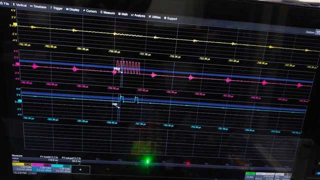
While checking in the oscilloscope, the data from the FPGA MISO pin is as expected but only Microcontroller is wrongly decoding as below.

The expected data is 0x08 but it is read as 0xf8. The error is very random and this is not happening in the same index always.

Code for receiving data from MISO:

void spi_receive(unsigned char *buff, uint8_t bytes)
{
    uint32_t i = 0;
    while(SSIDataGetNonBlocking(SSI0_BASE, &buff[0]))
                     {
                     }
    for (i = 0; i < bytes; i++) {
            MAP_SSIDataPut(SSI0_BASE, 0x00);
            MAP_SSIDataGet(SSI0_BASE, &buff[i]);
            MAP_SysCtlDelay(10000);
    }

}

Kindly support us to debug this further.

  • Hi Monica,

     How many bytes are passed to spi_receive()? Is it 2000? How do you know how many bytes are coming from the FPGA?

     What is the reason to insert the delay by calling MAP_SysCtlDelay(10000)? Does it make a difference if you shorten or increase the delay?

     Can you first initialize your array with a known pattern like 0x55? 

     Can you temporary code to your receive function that when it is not matching the expected data then you would immediately stop so you can debug what happens?

  • Hello Charles,

    The below code is where we read using spi_receive and to your question "How many bytes are passed to spi_receive()?" we write 257984 and expect 257984 data from the FPGA.

    const unsigned char g_pucDataArray[257984];

     void verify_flash(int CFG){

             unsigned char read_operation[4] = {0x73,0x00,0x00,0x00};
            unsigned char read_data[16];
    uint16_t count=0,ii;
            UARTprintf("Verifying internal flash....\n");
            for( k=0;k<num_chunks;k++){
                 cs_fpga(1);
                 MAP_SysCtlDelay(delay_1ms);
                 cs_fpga(0);
                 unsigned char  read_operation[4] = {0x73,0x00,0x00,0x00};
                 UARTprintf("\n");
                 spi_transmit(read_operation, 4);
                 spi_receive( read_data, 16);
                cs_fpga(1);
                if(areArraysEqual(&g_pucDataArray[k*16],read_data,16)){
                    MAP_SysCtlDelay(delay_1us);
                }

                else {
                    g_ui32LEDState = 5;
                    UARTprintf("Verify Fail\n");
                    for(ii=1; ii<=16; ii++){
                        UARTprintf("Expected[%d] :%02x Actual[%d] : %02x \n", ii, g_pucDataArray[k*16 + (ii-1)], ii, read_data[ii-1]);
                    }
                    udp_send_func(upcb,&verify_fail,sizeof(verify_fail));
                   // exit(0);
                    count++;
                }
            }


            UARTprintf("Verify Success\n");
            UARTprintf("count = %d\n",count);
        }

    Can you temporary code to your receive function that when it is not matching the expected data then you would immediately stop so you can debug what happens?

    Previously, we used exit(0) to immediately stop the code. However, to determine the number of failing counts, we commented out exit(0).

    What steps should be taken after the code stops to understand what occurred?

    The system works perfectly fine with Launchpad and our existing custom PCBs.

    This issue is only observed in the latest manufactured custom boards, even though there are no stack changes(wrt. SSI) between the old and new versions. As mentioned, this failure is very random, affecting only two or three counts at different indexes, and sometimes these counts are even correct.

    Could there be a problem with the microcontroller chip used in our latest boards, or are there other potential reasons?

    Thank you!

  • The below code is where we read using spi_receive and to your question "How many bytes are passed to spi_receive()?" we write 257984 and expect 257984 data from the FPGA.

    const unsigned char g_pucDataArray[257984];

    Hi,

       First of all, the MSP432E MCU has only 256kB of SRAM. How can you reserve more SRAM than what is physically available let alone your application will need SRAM for other functions. 

  • Hello,

    This variable is stored in Flash as it is a const.

    Firmware point of view, we could not find any issues as it is working perfectly fine in Launchpad and our existing custom PCBs but we are concerned on what could be wrong in the new PCBs.

    Previously, we used exit(0) to immediately stop the code. However, to determine the number of failing counts, we commented out exit(0).

    What steps should be taken after the code stops to understand what occurred?

    Can you please tell this?, i can further debug.

    Thanks

  • This variable is stored in Flash as it is a const.

    Ok. 

    Firmware point of view, we could not find any issues as it is working perfectly fine in Launchpad and our existing custom PCBs but we are concerned on what could be wrong in the new PCBs.

    Ok. You are saying the LaunchPad and your current PCB are working perfectly without any issue then I don't think there is an issue with your software. If you are only receiving wrong data on your new PCB then it is something to investigate on your hardware design. You should look at electrical characteristic carefully to see whether the received data is meeting the setup and hold time requirement on the MCU. You should particularly look at the S8 parameter. See below. 

    Previously, we used exit(0) to immediately stop the code. However, to determine the number of failing counts, we commented out exit(0).

    What steps should be taken after the code stops to understand what occurred?

    Can you please tell this?, i can further debug.

    I will suggest you compare the expected data with the received data. When they mismatch, you immediately put the code into a while loop. When you use the debugger to connect to the device, you can examine the received data in the variable. I will also suggest you first initialize the received variable to a known pattern. When a received data is stored to the variable, it will overwrite the initialized value. 

  • Hello Charles,

    You should particularly look at the S8 parameter.

    Probed for setup and hold time in the oscilloscope when it fails. setup time = 83.2ns and hold time = 116.6ns.

    SSI clock frequency is 5Mhz and also tried lowering the frequency till 500khz,still the issue is seen.

    When they mismatch, you immediately put the code into a while loop. When you use the debugger to connect to the device, you can examine the received data in the variable. I will also suggest you first initialize the received variable to a known pattern. When a received data is stored to the variable, it will overwrite the initialized value. 

    For every iteration initialized the read_data array with 0xAA and the data is overwritten. The received data is as below where the 5th index is wrong.

  • Hi,

      Can you zoom in to the transaction? This is not the transaction for the expected value 0x40. Can you zoom in to the transaction that shows the expected value equal to 0x40?

      Can you also confirm one more time that the same code running on the Launchpad and your prior PCB is working?

      What is the polarity and phase on the master side and what is the polarity and phase required by the slave side?