MSPM0G3507: SPI Communication - Prevent nCS line from going high in between address and data byte (8 bit transactions)

Part Number: MSPM0G3507

Tool/software:

Hi Team,

I am working with the MSPM0 and trying to connect it to an SBC (TCAN284X devices) via the SPI bus. 

I have everything pretty much working - but I can't find a flag or register where I can modify the behavior of the nCS pin. 

Currently the device will send the 7 bit address + r/w bit and then raise the nCS pin high before bringing it back low to send the 8-bit transaction or receive the 8-bit message. 

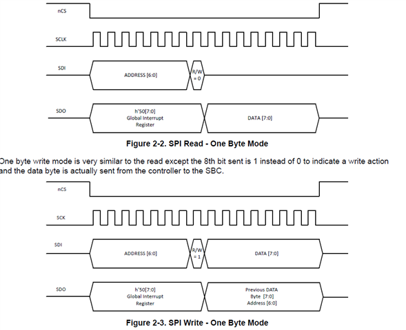
The SBC expects nCS to be low for the entire trasaction - including address and data - like below:

But the nCS pin on the MCU keeps doing this:


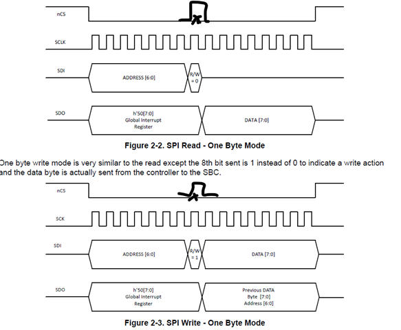
Where it pulls nCS high after every byte. 

I believe there should be a way to fix this where the entire transaction has nCS low instead of going low for each byte. As with what is currently happening now is that the SPI bus on the SBC gets reset everytime the nCS pin goes high in the middle of a transition. 

I tried just using a GPIO as nCS but the timing didn't look good and the output characteristics of the GPIO were not great in terms of how it looked - I am using the launchpad so it is a bit limited in all the pins I can access. 

So my main questions are:

1. Can I ensure that nCS is low for the entire transaction instead of just 1 byte (I have tried using 16bit transactions - but that also didn't seem to work) 

2. If I can do point 1 - how do I do that. 

Any help is greatly appreciated - we want to use MSPM0's as companion MCU's for a lot of our SBCs due to the CAN controller so this ask would help us not only with this problem but help us solidify a companion MCU with this device. 

Best,

Parker Dodson

  • Short answer: I recommend using a GPIO for nCS. There's no reason you can't use the same pin you're using now with the built-in nCS. What difficulties did you have with this?

    Slightly longer answer: TRM (SLAU846B) Sec 19.2.3.1 describes how /CS functions in each of the SPI modes. In two of those modes, /CS will stay low as long as you maintain a "continuous back-to-back" transfer; based on context and history I interpret this as "the Tx FIFO (+ shift register) never empties".

    For a sufficiently fast SPI, this is difficult to guarantee using software. DMA will probably accomplish it, but even that has no guarantees (the DMA can get "distracted"). The consequence of not keeping up (as you're seeing) is having your transaction broken up into two, and you won't even know it happened.

    Using a GPIO for nCS gives you full control over when it's asserted.

  • Hi Parker,

    Slightly longer answer: TRM (SLAU846B) Sec 19.2.3.1 describes how /CS functions in each of the SPI modes. In two of those modes, /CS will stay low as long as you maintain a "continuous back-to-back" transfer; based on context and history I interpret this as "the Tx FIFO (+ shift register) never empties".

    Show more details on Bruce introduction:

    This limits M0 as peripheral mode, I suppose you set M0 as controller, so this should not limit your controller behavior.

    Two method is introduced for it:

    1. Use SPH=1 mode, then the controller will NOT generate the CS pulse during the data frame.

    2. Disable the CS function, and use GPIO to act it as you tried before, I think it should work without any issues. I used to try with this method.

    B.R.

    Sal