MCU-PLUS-SDK-AM263PX: UART DMA

Part Number: MCU-PLUS-SDK-AM263PX
Other Parts Discussed in Thread: SYSCONFIG

Tool/software:

We are using UART DMA to transmit and receive data between the TI AM263Px and a modem, based on the example code: uart_echo_dma_lld_am263px-cc_r5fss0-0_nortos_ti-arm-clang.

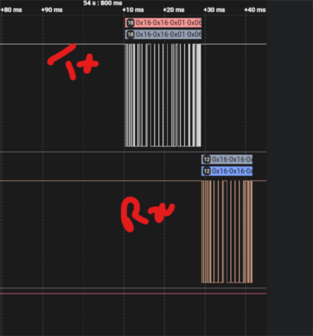
 Using a logic analyzer to monitor the TX and RX pins, we observed the following behavior:
When we transmit predefined data (18 bytes) to the modem, we immediately receive a response of 12 bytes from the modem.

As per our application requirements, we need to read this 12-byte response in two stages:
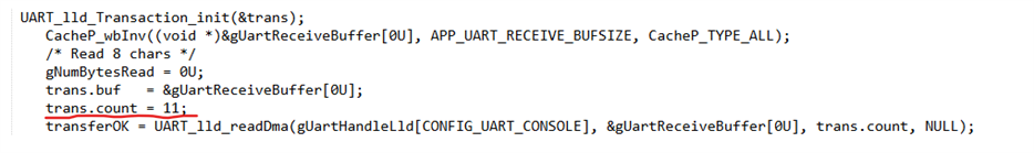
  • First, read 1 byte
  • Then, read the remaining 11 bytes

We are successfully receiving the first byte and getting a receive completion interrupt. However, during the second read attempt, we are not receiving remaining bytes as expected.

  • Hi ,

    Can you help me understand the Rx part a bit more? 

    For the remaining 11-bytes, what exactly happens? Do you receive the data partially? Do you not receive any bytes at all? Or is the second read attempt un-reliable and sometimes it reads data and sometimes it doesn't?

    Can you help me with some sample application which I can use to reproduce this issue on my end and figure out a solution?

    Regards,
    Shaunak

  • Hi Shashank, Thanks for the response.

    I am using API "UART_lld_readDma(gUartHandleLld[CONFIG_UART_CONSOLE], &gUartReceiveBuffer[0U], trans.count, NULL);"  to read the response.

    First time, I am giving trans.count = 1 and getting DMA Rx interrupt. Immediately when i tried to read second time for remaining 11 byets, I am calling same API with trans.count =11, I am not getting any DMA Rx interrupt.

    I used DMA LLD example code with minor modification for the testing. Please find file for  your reference

    /*
     *  Copyright (C) 2023 Texas Instruments Incorporated
     *
     *  Redistribution and use in source and binary forms, with or without
     *  modification, are permitted provided that the following conditions
     *  are met:
     *
     *    Redistributions of source code must retain the above copyright
     *    notice, this list of conditions and the following disclaimer.
     *
     *    Redistributions in binary form must reproduce the above copyright
     *    notice, this list of conditions and the following disclaimer in the
     *    documentation and/or other materials provided with the
     *    distribution.
     *
     *    Neither the name of Texas Instruments Incorporated nor the names of
     *    its contributors may be used to endorse or promote products derived
     *    from this software without specific prior written permission.
     *
     *  THIS SOFTWARE IS PROVIDED BY THE COPYRIGHT HOLDERS AND CONTRIBUTORS
     *  "AS IS" AND ANY EXPRESS OR IMPLIED WARRANTIES, INCLUDING, BUT NOT
     *  LIMITED TO, THE IMPLIED WARRANTIES OF MERCHANTABILITY AND FITNESS FOR
     *  A PARTICULAR PURPOSE ARE DISCLAIMED. IN NO EVENT SHALL THE COPYRIGHT
     *  OWNER OR CONTRIBUTORS BE LIABLE FOR ANY DIRECT, INDIRECT, INCIDENTAL,
     *  SPECIAL, EXEMPLARY, OR CONSEQUENTIAL DAMAGES (INCLUDING, BUT NOT
     *  LIMITED TO, PROCUREMENT OF SUBSTITUTE GOODS OR SERVICES; LOSS OF USE,
     *  DATA, OR PROFITS; OR BUSINESS INTERRUPTION) HOWEVER CAUSED AND ON ANY
     *  THEORY OF LIABILITY, WHETHER IN CONTRACT, STRICT LIABILITY, OR TORT
     *  (INCLUDING NEGLIGENCE OR OTHERWISE) ARISING IN ANY WAY OUT OF THE USE
     *  OF THIS SOFTWARE, EVEN IF ADVISED OF THE POSSIBILITY OF SUCH DAMAGE.
     */
    
    /* This example demonstrates the UART RX and TX operation by echoing char
     * that it recieves in blocking, interrupt mode of operation.
     * When user types 'quit', the application ends.
     */
    
    #include <string.h>
    #include <kernel/dpl/DebugP.h>
    #include "ti_drivers_config.h"
    #include "ti_drivers_open_close.h"
    #include <kernel/dpl/HwiP.h>
    #include <drivers/uart/v0/lld/uart_lld.h>
    #include "ti_board_open_close.h"
    #include <kernel/dpl/MutexArmP.h>
    #include <kernel/nortos/dpl/r5/HwiP_armv7r_vim.h>
    
    #define APP_UART_BUFSIZE              (200U)
    #define APP_UART_RECEIVE_BUFSIZE      (20)
    
    #define APP_UART_ASSERT_ON_FAILURE(transferOK, transaction) \
        do { \
            if((SystemP_SUCCESS != (transferOK)) || (UART_TRANSFER_STATUS_SUCCESS != transaction.status)) \
            { \
                DebugP_assert(FALSE); /* UART TX/RX failed!! */ \
            } \
        } while(0) \
    
    uint8_t gUartBuffer[APP_UART_BUFSIZE] __attribute__((aligned(128)));
    uint8_t gUartReceiveBuffer[APP_UART_RECEIVE_BUFSIZE] __attribute__((aligned(128)));
    uint8_t gUartRxBuff[APP_UART_RECEIVE_BUFSIZE] __attribute__((aligned(128)));
    volatile uint32_t gNumBytesRead = 0U, gNumBytesWritten = 0U;
    
    uint32_t gMutexArmWrite = MUTEX_ARM_LOCKED;
    uint32_t gMutexArmRead = MUTEX_ARM_LOCKED;
    
    uint8_t flag = 0;
    void uart_echo_dma_lld(void *args)
    {
        int32_t             transferOK;
        UART_Transaction    trans;
    
    
        Drivers_open();
        Board_driversOpen();
    
        DebugP_log("[UART] Echo example started ...\r\n");
    
        gUartObject[CONFIG_UART_CONSOLE].writeTransferMutex = &gMutexArmWrite;
        gUartObject[CONFIG_UART_CONSOLE].readTransferMutex = &gMutexArmRead;
    
        UART_lld_Transaction_init(&trans);
        uint32_t baseAdd = (uint32_t) AddrTranslateP_getLocalAddr(PLC_RESET_BASE_ADDR);
        GPIO_pinWriteHigh(baseAdd, PLC_RESET_PIN);
        ClockP_usleep(2000000);
        GPIO_pinWriteLow(baseAdd, PLC_RESET_PIN);
        ClockP_usleep(30000);
        GPIO_pinWriteHigh(baseAdd, PLC_RESET_PIN);
        ClockP_usleep(100000);
    
    
        gUartBuffer[0] = 0x16;
        gUartBuffer[1] = 0x16;
        gUartBuffer[2] =  0x01;
        gUartBuffer[3] =  0x06;
        gUartBuffer[4] =  0x00;
                gUartBuffer[5] =  0xFE;
                gUartBuffer[6] =  0x00;
                gUartBuffer[7] =  0x00;
                gUartBuffer[8] =  0x00;
                gUartBuffer[9] =  0x00;
                gUartBuffer[10] =  0x00;
                gUartBuffer[11] =  0x08;
                gUartBuffer[12] = 0x07;
                gUartBuffer[13] = 0x00;
                gUartBuffer[14] = 0x00;
                gUartBuffer[15] = 0x01;
                gUartBuffer[16] = 0x39;
                gUartBuffer[17] = 0xAD;
    
        /* Send entry string */
        gNumBytesWritten = 0U;
        trans.buf   = &gUartBuffer[0U];
        //strncpy(trans.buf,"This is uart echo test DMA non-blocking mode\r\nReceives 8 characters then echo's back. Please input..\r\n", APP_UART_BUFSIZE);
        trans.count = 18; //strlen(trans.buf);
        CacheP_wb((void *)trans.buf, trans.count, CacheP_TYPE_ALL);
        //transferOK = UART_lld_writeDma(gUartHandleLld[CONFIG_UART_CONSOLE], trans.buf, trans.count, NULL);
        transferOK = UART_lld_writeDma(gUartHandleLld[CONFIG_UART_CONSOLE], &gUartBuffer[0], trans.count, NULL);
    
        while(try_lock_mutex(gUartObject[CONFIG_UART_CONSOLE].writeTransferMutex) == MUTEX_ARM_LOCKED);
        APP_UART_ASSERT_ON_FAILURE(transferOK, trans);
    
        UART_lld_Transaction_init(&trans);
        CacheP_wbInv((void *)&gUartReceiveBuffer[0U], APP_UART_RECEIVE_BUFSIZE, CacheP_TYPE_ALL);
        /* Read 8 chars */
        gNumBytesRead = 0U;
        trans.buf   = &gUartReceiveBuffer[0U];
        trans.count = 1;
        transferOK = UART_lld_readDma(gUartHandleLld[CONFIG_UART_CONSOLE], &gUartReceiveBuffer[0U], trans.count, NULL);
    
        while(try_lock_mutex(gUartObject[CONFIG_UART_CONSOLE].readTransferMutex) == MUTEX_ARM_LOCKED);
        APP_UART_ASSERT_ON_FAILURE(transferOK, trans);
    
         UART_lld_Transaction_init(&trans);
            CacheP_wbInv((void *)&gUartReceiveBuffer[0U], APP_UART_RECEIVE_BUFSIZE, CacheP_TYPE_ALL);
            /* Read 8 chars */
            gNumBytesRead = 0U;
            trans.buf   = &gUartReceiveBuffer[0U];
            trans.count = 11;
            transferOK = UART_lld_readDma(gUartHandleLld[CONFIG_UART_CONSOLE], &gUartReceiveBuffer[0U], trans.count, NULL);
    
            while(try_lock_mutex(gUartObject[CONFIG_UART_CONSOLE].readTransferMutex) == MUTEX_ARM_LOCKED);
            APP_UART_ASSERT_ON_FAILURE(transferOK, trans);
            flag = 0;
    
            ClockP_usleep(3000000);
    }
    
    //    /* Echo chars entered */
    //    gNumBytesWritten = 0U;
    //    trans.buf   = &gUartReceiveBuffer[0U];
    //    trans.count = APP_UART_RECEIVE_BUFSIZE;
    //    transferOK = UART_lld_writeDma(gUartHandleLld[CONFIG_UART_CONSOLE], trans.buf, trans.count, NULL);
    //
    //    while(try_lock_mutex(gUartObject[CONFIG_UART_CONSOLE].writeTransferMutex) == MUTEX_ARM_LOCKED);
    //    APP_UART_ASSERT_ON_FAILURE(transferOK, trans);
    //
    //    /* Send exit string */
    //    gNumBytesWritten = 0U;
    //    trans.buf   = &gUartBuffer[0U];
    //    strncpy(trans.buf, "\r\nAll tests have passed!!\r\n", APP_UART_BUFSIZE);
    //    trans.count = strlen(trans.buf);
    //    CacheP_wb((void *)trans.buf, trans.count, CacheP_TYPE_ALL);
    //    transferOK = UART_lld_writeDma(gUartHandleLld[CONFIG_UART_CONSOLE], trans.buf, trans.count, NULL);
    ////
    //    while(try_lock_mutex(gUartObject[CONFIG_UART_CONSOLE].writeTransferMutex) == MUTEX_ARM_LOCKED);
    //    APP_UART_ASSERT_ON_FAILURE(transferOK, trans);
    //
        DebugP_log("All tests have passed!!\r\n");
    //}
    
        Board_driversClose();
        Drivers_close();
    
        return;
    }
    
    void UART_lld_writeCompleteCallback(void *args)
    {
        unlock_mutex(gUartObject[CONFIG_UART_CONSOLE].writeTransferMutex);
        return;
    }
    
    void UART_lld_readCompleteCallback(void *args)
    {
        unlock_mutex(gUartObject[CONFIG_UART_CONSOLE].readTransferMutex);
        flag = 1;
        CacheP_wbInv((void *)&gUartReceiveBuffer[0U], 9, CacheP_TYPE_ALL);
         UART_lld_readDma(gUartHandleLld[CONFIG_UART_CONSOLE], &gUartReceiveBuffer[0U],9, NULL);
        return;
    }
    

  • Hi,

    Is there any modification in the syscfg file compared to the standard SDK example?

    If yes, can you also share your example.syscfg file? 

    Regards,
    Shaunak

  • Hi Shaunak,

    We have used same sysconfig of SDK example. We are using UART4 instead of UART0

    /**
     * These arguments were used when this file was generated. They will be automatically applied on subsequent loads
     * via the GUI or CLI. Run CLI with '--help' for additional information on how to override these arguments.
     * @cliArgs --device "AM263Px" --part "AM263P4" --package "ZCZ_S" --context "r5fss0-0" --product "MCU_PLUS_SDK_AM263Px@10.02.00"
     * @v2CliArgs --device "AM263P4-Q1" --package "NFBGA (ZCZ-S)" --context "r5fss0-0" --product "MCU_PLUS_SDK_AM263Px@10.02.00"
     * @versions {"tool":"1.23.0+4000"}
     */
    
    /**
     * Import the modules used in this configuration.
     */
    const gpio            = scripting.addModule("/drivers/gpio/gpio", {}, false);
    const gpio1           = gpio.addInstance();
    const uart            = scripting.addModule("/drivers/uart/uart", {}, false);
    const uart1           = uart.addInstance();
    const uart2           = uart.addInstance();
    const debug_log       = scripting.addModule("/kernel/dpl/debug_log");
    const dpl_cfg         = scripting.addModule("/kernel/dpl/dpl_cfg");
    const mpu_armv7       = scripting.addModule("/kernel/dpl/mpu_armv7", {}, false);
    const mpu_armv71      = mpu_armv7.addInstance();
    const mpu_armv72      = mpu_armv7.addInstance();
    const mpu_armv73      = mpu_armv7.addInstance();
    const mpu_armv74      = mpu_armv7.addInstance();
    const default_linker  = scripting.addModule("/memory_configurator/default_linker", {}, false);
    const default_linker1 = default_linker.addInstance();
    const general         = scripting.addModule("/memory_configurator/general", {}, false);
    const general1        = general.addInstance();
    const region          = scripting.addModule("/memory_configurator/region", {}, false);
    const region1         = region.addInstance();
    const section         = scripting.addModule("/memory_configurator/section", {}, false);
    const section1        = section.addInstance();
    const section2        = section.addInstance();
    const section3        = section.addInstance();
    const section4        = section.addInstance();
    const section5        = section.addInstance();
    const section6        = section.addInstance();
    const section7        = section.addInstance();
    const section8        = section.addInstance();
    const section9        = section.addInstance();
    const section10       = section.addInstance();
    const section11       = section.addInstance();
    const section12       = section.addInstance();
    
    /**
     * Write custom configuration values to the imported modules.
     */
    gpio1.$name          = "PLC_RESET";
    gpio1.slewRate       = "high";
    gpio1.pu_pd          = "pu";
    gpio1.pinDir         = "OUTPUT";
    gpio1.GPIO_n.$assign = "SPI1_CLK";
    
    uart1.$name                     = "CONFIG_UART_CONSOLE";
    uart1.intrEnable                = "DMA";
    uart1.readCallbackFxn           = "UART_lld_readCompleteCallback";
    uart1.writeCallbackFxn          = "UART_lld_writeCompleteCallback";
    uart1.sdkInfra                  = "LLD";
    uart1.readMode                  = "CALLBACK";
    uart1.writeMode                 = "CALLBACK";
    uart1.baudRate                  = 9600;
    uart1.rxTrigLvl                 = "1";
    uart1.UART.$assign              = "UART4";
    uart1.UART.RXD.$assign          = "EQEP0_INDEX";
    uart1.UART.TXD.$assign          = "EQEP0_STROBE";
    uart1.uartRxConfigXbar.$name    = "CONFIG_DMA_TRIG_XBAR0";
    uart1.uartTxConfigXbar.$name    = "CONFIG_DMA_TRIG_XBAR1";
    uart1.uartTxConfigXbar.instance = "DMA_TRIG_XBAR_EDMA_MODULE_1";
    uart1.child.$name               = "drivers_uart_v2_uart_v2_template_lld0";
    
    const edma                  = scripting.addModule("/drivers/edma/edma", {}, false);
    const edma1                 = edma.addInstance({}, false);
    edma1.$name                 = "CONFIG_EDMA0";
    uart1.edmaDriver            = edma1;
    edma1.edmaRmDmaCh[0].$name  = "CONFIG_EDMA_RM0";
    edma1.edmaRmQdmaCh[0].$name = "CONFIG_EDMA_RM1";
    edma1.edmaRmTcc[0].$name    = "CONFIG_EDMA_RM2";
    edma1.edmaRmParam[0].$name  = "CONFIG_EDMA_RM3";
    
    uart2.$name            = "CONFIG_UART0";
    uart2.UART.$assign     = "UART0";
    uart2.UART.RXD.$assign = "UART0_RXD";
    uart2.UART.TXD.$assign = "UART0_TXD";
    uart2.child.$name      = "drivers_uart_v2_uart_v2_template0";
    
    mpu_armv71.$name             = "CONFIG_MPU_REGION0";
    mpu_armv71.size              = 31;
    mpu_armv71.attributes        = "Device";
    mpu_armv71.accessPermissions = "Supervisor RD+WR, User RD";
    mpu_armv71.allowExecute      = false;
    
    mpu_armv72.$name             = "CONFIG_MPU_REGION1";
    mpu_armv72.size              = 15;
    mpu_armv72.accessPermissions = "Supervisor RD+WR, User RD";
    
    mpu_armv73.$name             = "CONFIG_MPU_REGION2";
    mpu_armv73.baseAddr          = 0x80000;
    mpu_armv73.size              = 15;
    mpu_armv73.accessPermissions = "Supervisor RD+WR, User RD";
    
    mpu_armv74.$name             = "CONFIG_MPU_REGION3";
    mpu_armv74.accessPermissions = "Supervisor RD+WR, User RD";
    mpu_armv74.baseAddr          = 0x70000000;
    mpu_armv74.size              = 22;
    
    default_linker1.$name = "memory_configurator_default_linker0";
    
    general1.$name        = "CONFIG_GENERAL0";
    general1.linker.$name = "TIARMCLANG0";
    
    region1.$name                                = "MEMORY_REGION_CONFIGURATION0";
    region1.memory_region.create(11);
    region1.memory_region[0].type                = "TCMA";
    region1.memory_region[0].$name               = "R5F_VECS";
    region1.memory_region[0].size                = 0x40;
    region1.memory_region[0].auto                = false;
    region1.memory_region[1].type                = "TCMA";
    region1.memory_region[1].$name               = "R5F_TCMA";
    region1.memory_region[1].size                = 0x7FC0;
    region1.memory_region[2].type                = "TCMB";
    region1.memory_region[2].size                = 0x8000;
    region1.memory_region[2].$name               = "R5F_TCMB";
    region1.memory_region[3].$name               = "SBL";
    region1.memory_region[3].auto                = false;
    region1.memory_region[3].size                = 0x40000;
    region1.memory_region[4].$name               = "OCRAM";
    region1.memory_region[4].auto                = false;
    region1.memory_region[4].manualStartAddress  = 0x70040000;
    region1.memory_region[4].size                = 0x40000;
    region1.memory_region[5].type                = "FLASH";
    region1.memory_region[5].auto                = false;
    region1.memory_region[5].manualStartAddress  = 0x60100000;
    region1.memory_region[5].size                = 0x80000;
    region1.memory_region[5].$name               = "FLASH";
    region1.memory_region[6].$name               = "USER_SHM_MEM";
    region1.memory_region[6].auto                = false;
    region1.memory_region[6].manualStartAddress  = 0x701D0000;
    region1.memory_region[6].size                = 0x4000;
    region1.memory_region[6].isShared            = true;
    region1.memory_region[6].shared_cores        = ["r5fss0-1","r5fss1-0","r5fss1-1"];
    region1.memory_region[7].$name               = "LOG_SHM_MEM";
    region1.memory_region[7].auto                = false;
    region1.memory_region[7].manualStartAddress  = 0x701D4000;
    region1.memory_region[7].size                = 0x4000;
    region1.memory_region[7].isShared            = true;
    region1.memory_region[7].shared_cores        = ["r5fss0-1","r5fss1-0","r5fss1-1"];
    region1.memory_region[8].type                = "CUSTOM";
    region1.memory_region[8].$name               = "RTOS_NORTOS_IPC_SHM_MEM";
    region1.memory_region[8].auto                = false;
    region1.memory_region[8].manualStartAddress  = 0x72000000;
    region1.memory_region[8].size                = 0x3E80;
    region1.memory_region[8].isShared            = true;
    region1.memory_region[8].shared_cores        = ["r5fss0-1","r5fss1-0","r5fss1-1"];
    region1.memory_region[9].type                = "CUSTOM";
    region1.memory_region[9].$name               = "MAILBOX_HSM";
    region1.memory_region[9].auto                = false;
    region1.memory_region[9].manualStartAddress  = 0x44000000;
    region1.memory_region[9].size                = 0x3CE;
    region1.memory_region[9].isShared            = true;
    region1.memory_region[9].shared_cores        = ["r5fss0-1","r5fss1-0","r5fss1-1"];
    region1.memory_region[10].type               = "CUSTOM";
    region1.memory_region[10].$name              = "MAILBOX_R5F";
    region1.memory_region[10].auto               = false;
    region1.memory_region[10].manualStartAddress = 0x44000400;
    region1.memory_region[10].size               = 0x3CE;
    region1.memory_region[10].isShared           = true;
    region1.memory_region[10].shared_cores       = ["r5fss0-1","r5fss1-0","r5fss1-1"];
    
    section1.load_memory                  = "R5F_VECS";
    section1.group                        = false;
    section1.$name                        = "Vector Table";
    section1.output_section.create(1);
    section1.output_section[0].$name      = ".vectors";
    section1.output_section[0].palignment = true;
    
    section2.load_memory                  = "OCRAM";
    section2.$name                        = "Text Segments";
    section2.output_section.create(5);
    section2.output_section[0].$name      = ".text.hwi";
    section2.output_section[0].palignment = true;
    section2.output_section[1].$name      = ".text.cache";
    section2.output_section[1].palignment = true;
    section2.output_section[2].$name      = ".text.mpu";
    section2.output_section[2].palignment = true;
    section2.output_section[3].$name      = ".text.boot";
    section2.output_section[3].palignment = true;
    section2.output_section[4].$name      = ".text:abort";
    section2.output_section[4].palignment = true;
    
    section3.load_memory                  = "OCRAM";
    section3.$name                        = "Code and Read-Only Data";
    section3.output_section.create(2);
    section3.output_section[0].$name      = ".text";
    section3.output_section[0].palignment = true;
    section3.output_section[1].$name      = ".rodata";
    section3.output_section[1].palignment = true;
    
    section4.load_memory                  = "OCRAM";
    section4.$name                        = "Data Segment";
    section4.output_section.create(1);
    section4.output_section[0].$name      = ".data";
    section4.output_section[0].palignment = true;
    
    section5.load_memory                             = "OCRAM";
    section5.$name                                   = "Memory Segments";
    section5.output_section.create(3);
    section5.output_section[0].$name                 = ".bss";
    section5.output_section[0].output_sections_start = "__BSS_START";
    section5.output_section[0].output_sections_end   = "__BSS_END";
    section5.output_section[0].palignment            = true;
    section5.output_section[1].$name                 = ".sysmem";
    section5.output_section[1].palignment            = true;
    section5.output_section[2].$name                 = ".stack";
    section5.output_section[2].palignment            = true;
    
    section6.load_memory                              = "OCRAM";
    section6.$name                                    = "Stack Segments";
    section6.output_section.create(5);
    section6.output_section[0].$name                  = ".irqstack";
    section6.output_section[0].output_sections_start  = "__IRQ_STACK_START";
    section6.output_section[0].output_sections_end    = "__IRQ_STACK_END";
    section6.output_section[0].input_section.create(1);
    section6.output_section[0].input_section[0].$name = ". = . + __IRQ_STACK_SIZE;";
    section6.output_section[1].$name                  = ".fiqstack";
    section6.output_section[1].output_sections_start  = "__FIQ_STACK_START";
    section6.output_section[1].output_sections_end    = "__FIQ_STACK_END";
    section6.output_section[1].input_section.create(1);
    section6.output_section[1].input_section[0].$name = ". = . + __FIQ_STACK_SIZE;";
    section6.output_section[2].$name                  = ".svcstack";
    section6.output_section[2].output_sections_start  = "__SVC_STACK_START";
    section6.output_section[2].output_sections_end    = "__SVC_STACK_END";
    section6.output_section[2].input_section.create(1);
    section6.output_section[2].input_section[0].$name = ". = . + __SVC_STACK_SIZE;";
    section6.output_section[3].$name                  = ".abortstack";
    section6.output_section[3].output_sections_start  = "__ABORT_STACK_START";
    section6.output_section[3].output_sections_end    = "__ABORT_STACK_END";
    section6.output_section[3].input_section.create(1);
    section6.output_section[3].input_section[0].$name = ". = . + __ABORT_STACK_SIZE;";
    section6.output_section[4].$name                  = ".undefinedstack";
    section6.output_section[4].output_sections_start  = "__UNDEFINED_STACK_START";
    section6.output_section[4].output_sections_end    = "__UNDEFINED_STACK_END";
    section6.output_section[4].input_section.create(1);
    section6.output_section[4].input_section[0].$name = ". = . + __UNDEFINED_STACK_SIZE;";
    
    section7.load_memory                  = "OCRAM";
    section7.$name                        = "Initialization and Exception Handling";
    section7.output_section.create(3);
    section7.output_section[0].$name      = ".ARM.exidx";
    section7.output_section[0].palignment = true;
    section7.output_section[1].$name      = ".init_array";
    section7.output_section[1].palignment = true;
    section7.output_section[2].$name      = ".fini_array";
    section7.output_section[2].palignment = true;
    
    section8.load_memory                 = "USER_SHM_MEM";
    section8.type                        = "NOLOAD";
    section8.$name                       = "User Shared Memory";
    section8.group                       = false;
    section8.output_section.create(1);
    section8.output_section[0].$name     = ".bss.user_shared_mem";
    section8.output_section[0].alignment = 0;
    
    section9.load_memory                 = "LOG_SHM_MEM";
    section9.$name                       = "Log Shared Memory";
    section9.group                       = false;
    section9.type                        = "NOLOAD";
    section9.output_section.create(1);
    section9.output_section[0].$name     = ".bss.log_shared_mem";
    section9.output_section[0].alignment = 0;
    
    section10.load_memory                 = "RTOS_NORTOS_IPC_SHM_MEM";
    section10.type                        = "NOLOAD";
    section10.$name                       = "IPC Shared Memory";
    section10.group                       = false;
    section10.output_section.create(1);
    section10.output_section[0].$name     = ".bss.ipc_vring_mem";
    section10.output_section[0].alignment = 0;
    
    section11.load_memory                 = "MAILBOX_HSM";
    section11.type                        = "NOLOAD";
    section11.$name                       = "SIPC HSM Queue Memory";
    section11.group                       = false;
    section11.output_section.create(1);
    section11.output_section[0].$name     = ".bss.sipc_hsm_queue_mem";
    section11.output_section[0].alignment = 0;
    
    section12.load_memory                 = "MAILBOX_R5F";
    section12.$name                       = "SIPC R5F Queue Memory";
    section12.group                       = false;
    section12.type                        = "NOLOAD";
    section12.output_section.create(1);
    section12.output_section[0].$name     = ".bss.sipc_secure_host_queue_mem";
    section12.output_section[0].alignment = 0;
    

  • Hi Vinayaka,

    I don't have the complete setup to replicate this, but based on the discussion above, I can provide some inputs:

    1. For the second transfer, you don't get the interrupt, but check the UART registers to see if data has actually been received in the UART register.

    2. Can you test single byte transfers? Basically, set the trigger threshold for FIFO TO 1B and see if you receive interrupt for every byte. 

    Regards,
    Shaunak

  • Hi Vinayaka, 

    I also confirmed with IP experts, it should ideally be possible to change the threshold levels at run-time without needing any IP reset. So either there is some bug due to which the Rx interrupt didn't get triggered in the second case,

    Can you help me understand this please?

    1.We set the Rx threshold to "1" byte, get data over UART (18 Bytes) and then get the interrupt as expected. Can you please check how much data there is in the UART Rx FIFO at this point of time? Have we received all 18 Bytes?

    2. If we haven't received all 18 Bytes, then we expect the rest of the 17 Bytes to be delivered now and another Rx interrupt to be triggered. And before receiving these 17B, we re-configure the Rx threshold to 17. For this change to take place, you don't need any IP reset so just configuring the right registers through software should work. Since we are not receiving the interrupt, I believe there is some issue w.r.t how much data is there in the UART FIFO at this point. Can you please help me with these details to check further,

    Regards,
    Shaunak

  • Hi Shaunak, 

    Single byte transfer is working fine. Able to receive interrupt for every byte

    1. .If we set the Rx threshold to 1 byte, We receive an interrupt for every single byte and only 1 byte of data will be present in the Rx FIFO at that point in time.

    2.  For remaining 11 bytes of data, I configured Rx FIFO (trans.count =11) as shown below. However, I did not received any interrupt. I did observe that  next bytes of data were received in the Rx FIFO, but not the complete set of expected data.


    Rx Interrupt is not generated because the remaining 11 bytes of data have not yet been received in the Rx FIFO.

    However, When I use the UART LLD code, I am able to receive Rx interrupt for 1byte and immediately another Rx interrupt for 11 bytes of data


  • Hi Vinayaka,

    I'll raise a bug for the team to debug and verify the HLD driver code (Internal tracking link - jira.itg.ti.com/.../MCUSDK-14974).

    Glad to know the LLD code is working as you expect it to.

    Regards,
    Shaunak