Part Number: EK-TM4C129EXL
Tool/software:
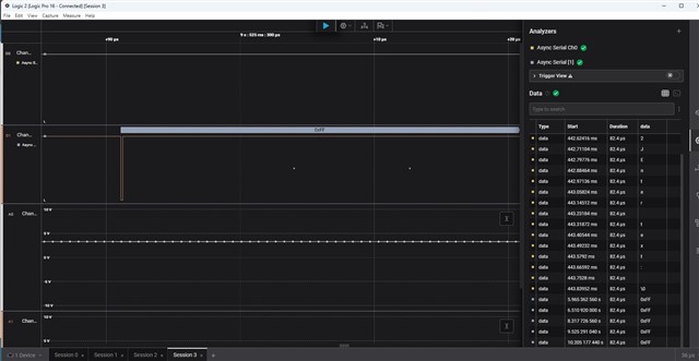
I modified demo project uart_echo a little bit to use UART7. I connected the eval board to my laptop through USB to TTL cable then started the debugger and Putty. The main function sent a prompt string to UART and I could see it in Putty. But if I typed something in Putty, it didn't echoed back. What I typed were supposed to be received by UARTIntHandler(my UART ISR) then wrote back to the UART. But that didn't happen. I set a breakpoint in the ISR at line after line: char c = MAP_UARTCharGetNonBlocking(UART7_BASE); The breakpoint was just hit once. It was after the program was launched. When I typed anything in Putty, the break was not hit. I don't know what was wrong.
Here is main()
void
UARTSend(const uint8_t *pui8Buffer, uint32_t ui32Count)
{
    //
    // Loop while there are more characters to send.
    //
    while(ui32Count--)
    {
        //
        // Write the next character to the UART.
        //
        MAP_UARTCharPutNonBlocking(UART7_BASE, *pui8Buffer++);
     // MAP_UARTCharPutNonBlocking(UART0_BASE, *pui8Buffer++);
    }
}

//*****************************************************************************
//
// This example demonstrates how to send a string of data to the UART.
//
//*****************************************************************************
int
main(void)
{
    //
    // Run from the PLL at 120 MHz.
    // Note: SYSCTL_CFG_VCO_240 is a new setting provided in TivaWare 2.2.x and
    // later to better reflect the actual VCO speed due to SYSCTL#22.
    //
    g_ui32SysClock = MAP_SysCtlClockFreqSet((SYSCTL_XTAL_25MHZ |
                                             SYSCTL_OSC_MAIN |
                                             SYSCTL_USE_PLL |
                                             SYSCTL_CFG_VCO_240), 120000000);

    //
    // Enable the GPIO port that is used for the on-board LED.
    //
    MAP_SysCtlPeripheralEnable(SYSCTL_PERIPH_GPION);

    //
    // Enable the GPIO pins for the LED (PN0).
    //
    MAP_GPIOPinTypeGPIOOutput(GPIO_PORTN_BASE, GPIO_PIN_0);

    //
    // Enable the peripherals used by this example.
    //
    MAP_SysCtlPeripheralEnable(SYSCTL_PERIPH_UART7);
    MAP_SysCtlPeripheralEnable(SYSCTL_PERIPH_GPIOC);

    //
    // Enable processor interrupts.
    //
    MAP_IntMasterEnable();

    //
    // Set GPIO C4 and C5 as UART pins.
    //
    MAP_GPIOPinConfigure(GPIO_PC4_U7RX);
    MAP_GPIOPinConfigure(GPIO_PC5_U7TX);
    MAP_GPIOPinTypeUART(GPIO_PORTC_BASE, GPIO_PIN_4 | GPIO_PIN_5);

    //
    // Configure the UART for 115,200, 8-N-1 operation.
    //
    MAP_UARTConfigSetExpClk(UART7_BASE, g_ui32SysClock, 115200,
                            (UART_CONFIG_WLEN_8 | UART_CONFIG_STOP_ONE |
                             UART_CONFIG_PAR_NONE));

    //
    // Enable the UART interrupt.
    //
    MAP_IntEnable(INT_UART7);
    MAP_UARTIntEnable(UART7_BASE, UART_INT_RX | UART_INT_RT);

    //
    // Prompt for text to be entered.
    //
    UARTSend((uint8_t *)"\033[2JEnter text: ", 16);

    //
    // Loop forever echoing data through the UART.
    //
    while(1)
    {
    }
}
ISR:
void
UARTIntHandler(void)
{
    uint32_t ui32Status;

    //
    // Get the interrrupt status.
    //
    ui32Status = MAP_UARTIntStatus(UART7_BASE, true);

    //
    // Clear the asserted interrupts.
    //
    MAP_UARTIntClear(UART7_BASE, ui32Status);

    //
    // Loop while there are characters in the receive FIFO.
    //
    while(MAP_UARTCharsAvail(UART7_BASE))
    {
        //
        // Read the next character from the UART and write it back to the UART.
        //
        /*
        MAP_UARTCharPutNonBlocking(UART7_BASE,
                                   MAP_UARTCharGetNonBlocking(UART7_BASE));
        */

        char c = MAP_UARTCharGetNonBlocking(UART7_BASE);

        MAP_UARTCharPutNonBlocking(UART7_BASE, c);
        //
        // Blink the LED to show a character transfer is occuring.
        //
        MAP_GPIOPinWrite(GPIO_PORTN_BASE, GPIO_PIN_0, GPIO_PIN_0);

        //
        // Delay for 1 millisecond.  Each SysCtlDelay is about 3 clocks.
        //
        SysCtlDelay(g_ui32SysClock / (1000 * 3));

        //
        // Turn off the LED
        //
        MAP_GPIOPinWrite(GPIO_PORTN_BASE, GPIO_PIN_0, 0);
    }
}
startup file to set ISR on UART7
//*****************************************************************************
//
// startup_ccs.c - Startup code for use with TI's Code Composer Studio.
//
// Copyright (c) 2013-2020 Texas Instruments Incorporated.  All rights reserved.
// Software License Agreement
//
// Texas Instruments (TI) is supplying this software for use solely and
// exclusively on TI's microcontroller products. The software is owned by
// TI and/or its suppliers, and is protected under applicable copyright
// laws. You may not combine this software with "viral" open-source
// software in order to form a larger program.
//
// THIS SOFTWARE IS PROVIDED "AS IS" AND WITH ALL FAULTS.
// NO WARRANTIES, WHETHER EXPRESS, IMPLIED OR STATUTORY, INCLUDING, BUT
// NOT LIMITED TO, IMPLIED WARRANTIES OF MERCHANTABILITY AND FITNESS FOR
// A PARTICULAR PURPOSE APPLY TO THIS SOFTWARE. TI SHALL NOT, UNDER ANY
// CIRCUMSTANCES, BE LIABLE FOR SPECIAL, INCIDENTAL, OR CONSEQUENTIAL
// DAMAGES, FOR ANY REASON WHATSOEVER.
//
// This is part of revision 2.2.0.295 of the EK-TM4C129EXL Firmware Package.
//
//*****************************************************************************

#include <stdint.h>
#include "inc/hw_nvic.h"
#include "inc/hw_types.h"

//*****************************************************************************
//
// Forward declaration of the default fault handlers.
//
//*****************************************************************************
void ResetISR(void);
static void NmiSR(void);
static void FaultISR(void);
static void IntDefaultHandler(void);

//*****************************************************************************
//
// External declaration for the reset handler that is to be called when the
// processor is started
//
//*****************************************************************************
extern void _c_int00(void);

//*****************************************************************************
//
// Linker variable that marks the top of the stack.
//
//*****************************************************************************
extern uint32_t __STACK_TOP;

//*****************************************************************************
//
// External declaration for the interrupt handler used by the application.
//
//*****************************************************************************
extern void UARTIntHandler(void);

//*****************************************************************************
//
// The vector table.  Note that the proper constructs must be placed on this to
// ensure that it ends up at physical address 0x0000.0000 or at the start of
// the program if located at a start address other than 0.
//
//*****************************************************************************
#pragma DATA_SECTION(g_pfnVectors, ".intvecs")
void (* const g_pfnVectors[])(void) =
{
    (void (*)(void))((uint32_t)&__STACK_TOP),
                                            // The initial stack pointer
    ResetISR,                               // The reset handler
    NmiSR,                                  // The NMI handler
    FaultISR,                               // The hard fault handler
    IntDefaultHandler,                      // The MPU fault handler
    IntDefaultHandler,                      // The bus fault handler
    IntDefaultHandler,                      // The usage fault handler
    0,                                      // Reserved
    0,                                      // Reserved
    0,                                      // Reserved
    0,                                      // Reserved
    IntDefaultHandler,                      // SVCall handler
    IntDefaultHandler,                      // Debug monitor handler
    0,                                      // Reserved
    IntDefaultHandler,                      // The PendSV handler
    IntDefaultHandler,                      // The SysTick handler
    IntDefaultHandler,                      // GPIO Port A
    IntDefaultHandler,                      // GPIO Port B
    IntDefaultHandler,                      // GPIO Port C
    IntDefaultHandler,                      // GPIO Port D
    IntDefaultHandler,                      // GPIO Port E
    IntDefaultHandler,                         // UART0 Rx and Tx
    IntDefaultHandler,                      // UART1 Rx and Tx
    IntDefaultHandler,                      // SSI0 Rx and Tx
    IntDefaultHandler,                      // I2C0 Master and Slave
    IntDefaultHandler,                      // PWM Fault
    IntDefaultHandler,                      // PWM Generator 0
    IntDefaultHandler,                      // PWM Generator 1
    IntDefaultHandler,                      // PWM Generator 2
    IntDefaultHandler,                      // Quadrature Encoder 0
    IntDefaultHandler,                      // ADC Sequence 0
    IntDefaultHandler,                      // ADC Sequence 1
    IntDefaultHandler,                      // ADC Sequence 2
    IntDefaultHandler,                      // ADC Sequence 3
    IntDefaultHandler,                      // Watchdog timer
    IntDefaultHandler,                      // Timer 0 subtimer A
    IntDefaultHandler,                      // Timer 0 subtimer B
    IntDefaultHandler,                      // Timer 1 subtimer A
    IntDefaultHandler,                      // Timer 1 subtimer B
    IntDefaultHandler,                      // Timer 2 subtimer A
    IntDefaultHandler,                      // Timer 2 subtimer B
    IntDefaultHandler,                      // Analog Comparator 0
    IntDefaultHandler,                      // Analog Comparator 1
    IntDefaultHandler,                      // Analog Comparator 2
    IntDefaultHandler,                      // System Control (PLL, OSC, BO)
    IntDefaultHandler,                      // FLASH Control
    IntDefaultHandler,                      // GPIO Port F
    IntDefaultHandler,                      // GPIO Port G
    IntDefaultHandler,                      // GPIO Port H
    IntDefaultHandler,                      // UART2 Rx and Tx
    IntDefaultHandler,                      // SSI1 Rx and Tx
    IntDefaultHandler,                      // Timer 3 subtimer A
    IntDefaultHandler,                      // Timer 3 subtimer B
    IntDefaultHandler,                      // I2C1 Master and Slave
    IntDefaultHandler,                      // CAN0
    IntDefaultHandler,                      // CAN1
    IntDefaultHandler,                      // Ethernet
    IntDefaultHandler,                      // Hibernate
    IntDefaultHandler,                      // USB0
    IntDefaultHandler,                      // PWM Generator 3
    IntDefaultHandler,                      // uDMA Software Transfer
    IntDefaultHandler,                      // uDMA Error
    IntDefaultHandler,                      // ADC1 Sequence 0
    IntDefaultHandler,                      // ADC1 Sequence 1
    IntDefaultHandler,                      // ADC1 Sequence 2
    IntDefaultHandler,                      // ADC1 Sequence 3
    IntDefaultHandler,                      // External Bus Interface 0
    IntDefaultHandler,                      // GPIO Port J
    IntDefaultHandler,                      // GPIO Port K
    IntDefaultHandler,                      // GPIO Port L
    IntDefaultHandler,                      // SSI2 Rx and Tx
    IntDefaultHandler,                      // SSI3 Rx and Tx
    IntDefaultHandler,                      // UART3 Rx and Tx
    IntDefaultHandler,                      // UART4 Rx and Tx
    IntDefaultHandler,                      // UART5 Rx and Tx
    IntDefaultHandler,                      // UART6 Rx and Tx
    UARTIntHandler,                      // UART7 Rx and Tx
    IntDefaultHandler,                      // I2C2 Master and Slave
    IntDefaultHandler,                      // I2C3 Master and Slave
    IntDefaultHandler,                      // Timer 4 subtimer A
    IntDefaultHandler,                      // Timer 4 subtimer B
    IntDefaultHandler,                      // Timer 5 subtimer A
    IntDefaultHandler,                      // Timer 5 subtimer B
    IntDefaultHandler,                      // FPU
    0,                                      // Reserved
    0,                                      // Reserved
    IntDefaultHandler,                      // I2C4 Master and Slave
    IntDefaultHandler,                      // I2C5 Master and Slave
    IntDefaultHandler,                      // GPIO Port M
    IntDefaultHandler,                      // GPIO Port N
    0,                                      // Reserved
    IntDefaultHandler,                      // Tamper
    IntDefaultHandler,                      // GPIO Port P (Summary or P0)
    IntDefaultHandler,                      // GPIO Port P1
    IntDefaultHandler,                      // GPIO Port P2
    IntDefaultHandler,                      // GPIO Port P3
    IntDefaultHandler,                      // GPIO Port P4
    IntDefaultHandler,                      // GPIO Port P5
    IntDefaultHandler,                      // GPIO Port P6
    IntDefaultHandler,                      // GPIO Port P7
    IntDefaultHandler,                      // GPIO Port Q (Summary or Q0)
    IntDefaultHandler,                      // GPIO Port Q1
    IntDefaultHandler,                      // GPIO Port Q2
    IntDefaultHandler,                      // GPIO Port Q3
    IntDefaultHandler,                      // GPIO Port Q4
    IntDefaultHandler,                      // GPIO Port Q5
    IntDefaultHandler,                      // GPIO Port Q6
    IntDefaultHandler,                      // GPIO Port Q7
    IntDefaultHandler,                      // GPIO Port R
    IntDefaultHandler,                      // GPIO Port S
    IntDefaultHandler,                      // SHA/MD5 0
    IntDefaultHandler,                      // AES 0
    IntDefaultHandler,                      // DES3DES 0
    IntDefaultHandler,                      // LCD Controller 0
    IntDefaultHandler,                      // Timer 6 subtimer A
    IntDefaultHandler,                      // Timer 6 subtimer B
    IntDefaultHandler,                      // Timer 7 subtimer A
    IntDefaultHandler,                      // Timer 7 subtimer B
    IntDefaultHandler,                      // I2C6 Master and Slave
    IntDefaultHandler,                      // I2C7 Master and Slave
    IntDefaultHandler,                      // HIM Scan Matrix Keyboard 0
    IntDefaultHandler,                      // One Wire 0
    IntDefaultHandler,                      // HIM PS/2 0
    IntDefaultHandler,                      // HIM LED Sequencer 0
    IntDefaultHandler,                      // HIM Consumer IR 0
    IntDefaultHandler,                      // I2C8 Master and Slave
    IntDefaultHandler,                      // I2C9 Master and Slave
    IntDefaultHandler                       // GPIO Port T
};

//*****************************************************************************
//
// This is the code that gets called when the processor first starts execution
// following a reset event.  Only the absolutely necessary set is performed,
// after which the application supplied entry() routine is called.  Any fancy
// actions (such as making decisions based on the reset cause register, and
// resetting the bits in that register) are left solely in the hands of the
// application.
//
//*****************************************************************************
void
ResetISR(void)
{
    //
    // Jump to the CCS C initialization routine.  This will enable the
    // floating-point unit as well, so that does not need to be done here.
    //
    __asm("    .global _c_int00\n"
          "    b.w     _c_int00");
}

//*****************************************************************************
//
// This is the code that gets called when the processor receives a NMI.  This
// simply enters an infinite loop, preserving the system state for examination
// by a debugger.
//
//*****************************************************************************
static void
NmiSR(void)
{
    //
    // Enter an infinite loop.
    //
    while(1)
    {
    }
}

//*****************************************************************************
//
// This is the code that gets called when the processor receives a fault
// interrupt.  This simply enters an infinite loop, preserving the system state
// for examination by a debugger.
//
//*****************************************************************************
static void
FaultISR(void)
{
    //
    // Enter an infinite loop.
    //
    while(1)
    {
    }
}

//*****************************************************************************
//
// This is the code that gets called when the processor receives an unexpected
// interrupt.  This simply enters an infinite loop, preserving the system state
// for examination by a debugger.
//
//*****************************************************************************
static void
IntDefaultHandler(void)
{
    //
    // Go into an infinite loop.
    //
    while(1)
    {
    }
}