MSPM0C1103-Q1: Error connecting to the target: DAP Connection Error.[MSPM0C1103]

Part Number: MSPM0C1103-Q1
Other Parts Discussed in Thread: MSPM0C1103, LP-MSPM0C1104, UNIFLASH, MSPM0C1104, SEGGER

Tool/software:

 Hi team,

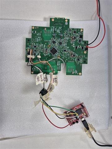
 I'm using the MSPM0C1103 LaunchPad with the XDS110 USB Debug Probe and CCS. Initially, I was able to flash the .out file successfully a couple of times,
  but after that I started getting the following.
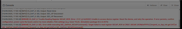
 Error: 
 CS_DAP_0: Error connecting to the target: DAP Connection Error. This could be caused by the device having gone to low power mode. Try forcing an external reset. If the error persists, try forcing BSL, a Mass   erase or a   Factory Reset.

  Sometimes the device responds again after a reset or power cycle, but other times it remains completely inaccessible. I also tried the MSPM0_Mailbox_FactoryReset_Manual script, but it’s not working reliably on this    board. Could you please suggest a permanent  fix for this issue? 


 Thanks and Regards
Ramalingam Pachamuthu.

  • Hi Ramalingam,

    Can you take a picture of the board you are using?

    I also tried the MSPM0_Mailbox_FactoryReset_Manual script, but it’s not working reliably on this    board.

    What do you mean by "not working reliably?"

    Are you disabling the NRST pin or using it for something else?

    What is the program that you are flashing onto the board? What pins/peripherals does it use? What low power mode policy is being used (if any).

    Best,

    Owen

  • Hi Owen,

    I’m working with the LP-MSPM0C1104 LaunchPad, which contains the MSPM0C1103 device, and using the XDS110 USB Debug Probe through CCS. I was able to flash the firmware successfully a couple of times, but later it started failing with the following error:

    Error connecting to the target: Connection to MSPM0 core failed. Possible root causes:

    • Debug access within NONMAIN was disabled or enabled with password

    • Peripheral misconfiguration (e.g., improper watchdog or clock)

    As suggested earlier in the forum, I followed the recovery steps and used the MSPM0_Mailbox_FactoryReset_Manual script via CCS. This resolved the issue initially and allowed me to flash again. However, a similar error has now reappeared:

    CS_DAP_0: Error connecting to the target: DAP Connection Error. This may be caused by the device entering low power mode. It suggests trying an external reset, BSL mode, mass erase, or factory reset.

    I’ve repeated the same recovery steps using the XDS110 USB Debug Probe, but the issue persists. That’s what I meant when I said the solution is “not working reliably” — it worked once, but is no longer effective in resolving the current issue.

    Firmware Overview:

    The firmware includes a GPIO-based MDIO/MDC implementation, bit-banged using two GPIOs to initialize a Marvell PHY.
    Can you please help me on this ji.

    Thanks ,
    Ramalingam.


  • Hi Ramalingam,

    I understand what you are using, but if you could provide more information it would allow me to assist you better.

    1. Can you take a picture of the board you are using? This will help me see exactly how your board is set up and the board version you are using.
    2. Are you disabling the NRST pin or using it for something else?
    3. What low power mode policy is being used? (if any)
    4. What exact pins/peripherals does your program use?
    5. Is it possible for you to share the project?

    Best,

    Owen

  • Hi Owen Li,

     Regarding your question "Are you disabling the NRST pin or using it for something else?"
    I followed the  below steps for recover from this issue as mentioned in the forum.

    1) put the uC in unpower mode.
    2) put the NRST pin to gnd (by direct shortcu to gnd).
    3) put the uC in power mode.
    4) run the script  "MSPM0_Mailbox_FactoryReset_Manual" via CCS and Uniflash.
    5) remove the short cut from NRST.


    after this i am facing this error.
    Trouble Writing Register SECAP_TCR: (Error -2131 @ 0x20204) Unable to access device register. Reset the device, and retry the operation. If error persists, confirm configuration, power-cycle the board, and/or try more reliable JTAG settings (e.g. lower TCLK). (Emulation package 20.1.0.3372) [6/20/2025, 5:37:25 PM] [ERROR] CS_DAP_0: GEL: Error while executing GEL_DAPInit_SECAPCommand(): Target failed to write register SECAP_TCR at 'REG'::SECAP_TCR=command

    Can you support me in this ?

    Thanks and Regards
    Ramalingam

  • Hi Ramalingan,

    The reason why you are experiencing an issue with those steps is because you're pulling the NRST pin to ground when attempting to run the script. The debugger can't connect to the device because it was being reset when you were attempting to run the script.

    Best,

    Owen

  • Hi Owen,

               Here I am providing the details for your reference


                     Figure 1
                
                 1.NRST Pin: The NRST debug signal is directly connected to the MCU’s NRST pin in this setup.
                 2.Low Power Mode: No low power mode policy is being used in this project.
                 3.Pins/Peripherals Used
                   
                     Figure 2

                   I used UniFlash  and CCS to flash the firmware, and initially it succeeded. However, we later encountered the following error.


                   Figure 3

                     To recover, we ran the MSPM0_Mailbox_FactoryReset_Auto script using the same setup, as suggested in the MSPM0 documentation.                               However, after executing the script, we encountered a new error.
                     
                   Figure 4
                  
                   I hope these details are sufficient to help diagnose the issue. Could you please support me on this?

    Thanks and Regards,
    Ramalingam.P


  • Hi Ramalingam,

    Thanks for providing all of these details.

    I believe I misspoke in my previous reply. It is a good protocol to hold the reset to GND when performing the script to ensure that the CPU doesn't wake and prevent itself from connecting to the debugger. I notice that the PCB seems to be powered in the top right corner of the image you shared. Ensure that this is also disconnected so that the PCB is not being supplied power. Try the same steps you tried previously and ensure you are using the MANUAL script rather than the automatic one.

    1) put the uC in unpower mode.
    2) put the NRST pin to gnd (by direct shortcu to gnd).
    3) put the uC in power mode.
    4) run the script  "MSPM0_Mailbox_FactoryReset_Manual" via CCS and Uniflash.
    5) remove the short cut from NRST.

    Here you noted that you tried the Auto script:

    To recover, we ran the MSPM0_Mailbox_FactoryReset_Auto script using the same setup, as suggested in the MSPM0 documentation.                               However, after executing the script, we encountered a new error.
    1. Is the board in-between the MSPM0C1104 LaunchPad and your custom PCB a level shifter?
    2. Are you writing anything to NONMAIN memory?
    3. To clarify again, you can program the device, but afterward never access the device again?

    Best,

    Owen

  • Hi  Owen,
                       Regarding your note: "You tried the Auto script"
                       I actually tried both the manual and auto factory reset scripts.

    when I used the Mailbox Factory Reset Manual script, I followed the steps below:

    1. Powered down the microcontroller

    2. Pulled the NRST pin to ground (direct short to GND)

    3. Powered up the microcontroller

    4. Ran the script MSPM0_Mailbox_FactoryReset_Manual via CCS and UniFlash

    5. Removed the NRST shortcut

    I also tried the Mailbox Factory Reset Auto script using the same setup I mentioned earlier.

    In both cases, I encountered the following error:


    1. Is the board in-between the MSPM0C1104 LaunchPad and your custom PCB a level shifter?
      yes 
    2. Are you writing anything to NONMAIN memory?
      No 
    3. To clarify again, you can program the device, but afterward never access the device again?
      couple of times we could flashed . later we fached this error.

      Is the board between the MSPM0C1104 LaunchPad and our custom PCB a level shifter? Yes.

      Are we writing anything to NONMAIN memory? No.

      Can we program the device, but afterward never access it again? Yes — we were able to flash the device a couple of times successfully. Later, we started encountering this error and lost access.

    Thanks and Regards
    Ramalingam.P
                    

  • Hi Ramalingam,

    So when you perform the script to factory reset, the LaunchPad and your custom PCB are powered off? Ensure that both are disconnected to power to guarantee that absolutely no power is being supplied. 

    Is it possible for you to try the connection without the level shifter? Or is the custom PCB not rated for 3.3V?

    Something you can check is the current from the level shifter. There's a slight chance that driving too many pins can degrade the signal integrity.

    Do you experience the issue if you set up the LaunchPad to flash the MSPM0C1104 on the LaunchPad?

    The error on the Factory Reset makes me want to believe that the board may not be receiving power or something related to JTAG:

    Here's the link to the Debugging JTAG Guide.

    Best,

    Owen

  • Hi Owen,

    Currently, we’re facing the same issue with two boards. Yesterday, we followed the recovery steps below:

    1. Powered down the microcontroller

    2. Pulled the NRST pin to ground (direct short to GND)

    3. Powered up the microcontroller

    4. Ran the script MSPM0_Mailbox_FactoryReset_Manual via CCS and UniFlash

    5. Removed the NRST shortcut

    Using this method, we were able to successfully recover one of the boards. However, the second board is still showing the same issue, even after repeating the exact same steps.

    Could you help us understand what might be happening here and support us in resolving it?

    Thanks,
    Ramalingam

  • Hi Ramalingam,

    Is it possible for you to do this without the level shifter?

    My thought is that you are either putting the device into a bad state and that is why it may continue to be unable to be connected to, there may be a power issue, or there is an issue with the JTAG.

    Is it possible for you to share your code so I can do a review?

    Best,

    Owen

  • Hi Owen,

    We’ve been encountering an intermittent issue while flashing firmware to the MSPM0C1103. I’ll explain the scenario step-by-step:

    Initially, we used the J-Flash tool with J-Link to flash the board successfully about five times. Later, we selected the "Erase Chip" option in J-Flash. After that, the board started showing errors, such as entering low-power mode unexpectedly.

    To recover, we used the Factory Reset (Auto) feature in CCS, which allowed us to flash the firmware again. However, after flashing, the board failed once more.

    Could this recurring failure be caused by the initial use of the "Erase Chip" option? Even though we were able to recover using CCS, the issue seems to reappear after flashing. We’d like to understand why this is happening and how to prevent it.

    Also, we have another working board, and the requirement is to erase and reprogram only a specific range of code in memory — not the entire flash.

    Is it safe to do this on MSPM0C1103 using J-Link (Segger) tools, or could partial erase/write operations cause the MCU to enter a locked or unrecoverable state?

    Thanks
    Ramalingam.P

  • Hi Ramalingam,

    Thanks for providing more context. Please answer these questions so I can help you:

    1. What version of the tool are you using?
    2. What range of memory are you partially erasing and reprogramming for the other board?
    3. Can you try connecting to the device without the level shifter?
    4. Have you referenced this guide?

    Best,

    Owen

  • Hi owwn Li,

    What version of the tool are you using? We are using J-Flash v8.56.

    What range of memory are you partially erasing and reprogramming for the other board? We are exploring whether it's possible to erase and reprogram the main memory by specifying the address range. For example, flashing only from 0x0000 to 0x2000 instead of the entire memory.

    Can you try connecting to the device without the level shifter? Yes, we have tried connecting without the level shifter.

    Have you referenced this guide? Yes, we are using the official SEGGER J-Flash tool from this link: https://www.segger.com/downloads/jlink/

    Thanks
    Ramalingam.P

  • Hi Ramalingam,

    I don't suspect the version to be a major issue, but I believe there are newer versions of the software that may be worth trying.

    As for the memory between 0x0000 and 0x2000, I don't think this is an issue either since it is all of the code region:

    I will have to look into the effects of Erase Chip using J-Link on the MSPM0C1103.

    After seeing the issue, are you able to recover the device? Is it intermittent as well?

    Best,

    Owen

  • Hi Owen,
                   

                 After seeing the issue, are you able to recover the device? Is it intermittent as well?
                 No, I’m not able to recover the device even after trying a factory reset. The issue persists,
                and it doesn’t appear to be intermittent.

    Thanks 
    Ramalingam.P

  • Hi Ramalingam,

    Thanks for clarifying. I will look into this with the software team as well. I will be out of office tomorrow, so I will try to have some steps for you to try on Monday.

    Best,

    Owen

  • Hi Ramalingam,
    I recommend to now open a new thread for this E2E since it has become too long. I'll close it now.

    Best Regards,

    Diego Abad